


11
INSTALLATION INSTRUCTIONS
SITE REQUIREMENTS
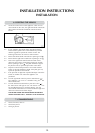
4. VENTILATION
5. APPLIANCE LOCATION
4.1 This appliance requires no additional ventilation.
5.1 It is not necessary to site the appliance on a non-
combustible floor. However, for practical reasons, the floor
should be flat and solid to allow the appliance to be
levelled and secured in place.
5.2 This appliance may be situated anywhere in the room but
due consideration should be taken to ensure that it is sited
within the constraints of the allowable flue configuration.
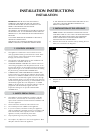
5.3 If the appliance is to be sited against a combustible wall, a
clearance of 50mm should be allowed between the wall
and the rear of the appliance.
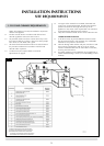
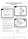
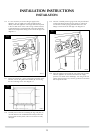
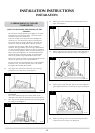
2.3 TOP FLUE VERTICAL KIT (8524/8524AN)
Vertical from the top of the appliance (See Diagram 1C).
A minimum vertical rise 3m (9’10") to a maximum 10m
(32’10"). The basic kit comprises:
2 x 1m lengths
1 x 1m terminal length
1 x 52mm restrictor
1 x 47mm restrictor
Extra lengths may be added from the list below.
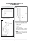
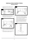
2.4 TOP FLUE VERTICAL OFFSET KIT (8530)
Used with kit 8524 only (See diagram 5)
A minimum rise of 500mm (19
1
/
2
˝) is required to the first
bend. Refer to diagram 4.
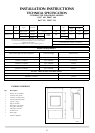
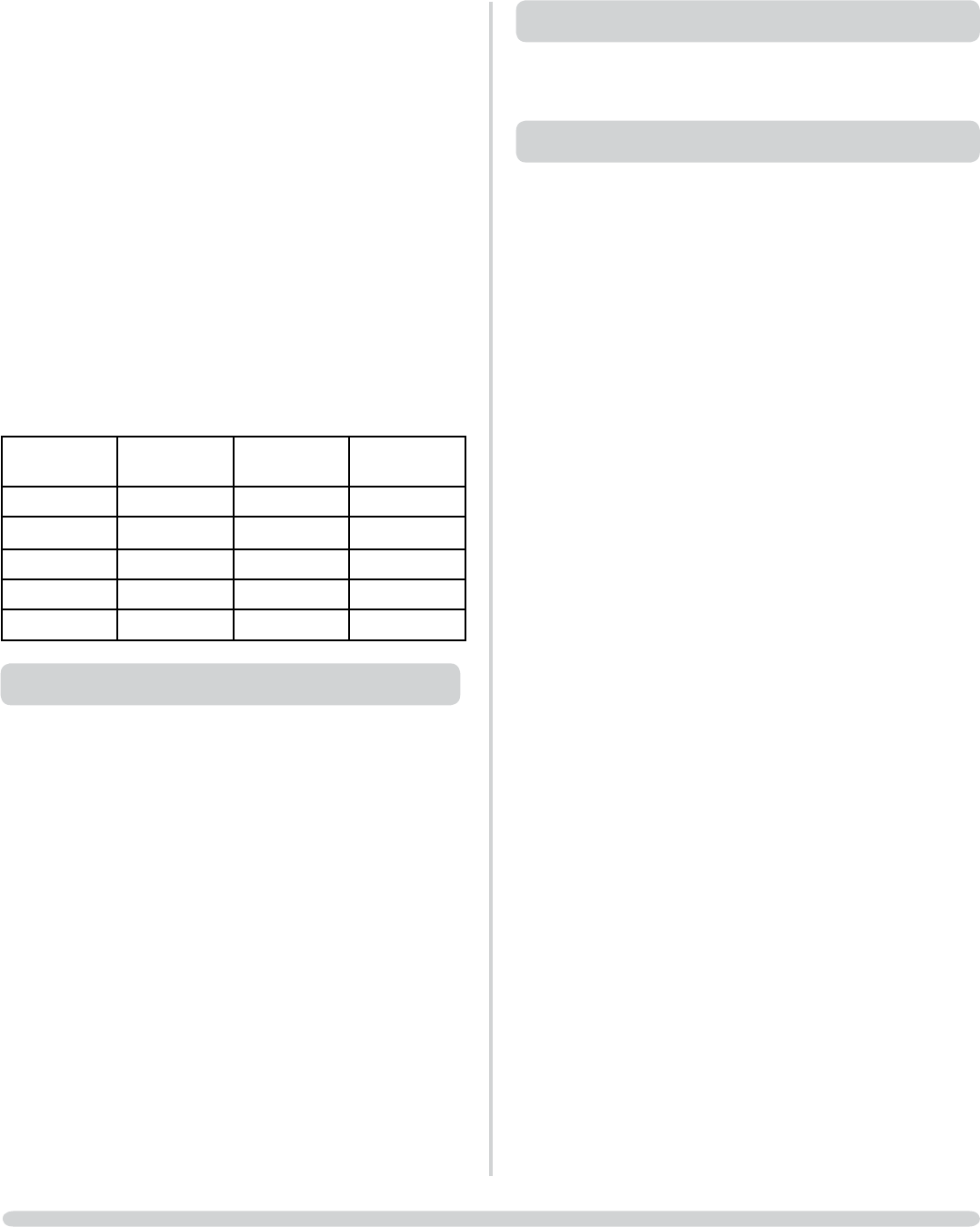
2.5 OPTIONAL FLUE LENGTHS & BENDS
All flue components are 150mm diameter (6")
Nominal
Length
Actual Length Stainless
Finish
Anthracite
Finish
200mm 140mm 8527 8527AN
500mm 440mm 8528 8528AN
1000mm 940mm 8529 8529AN
40° Bend N/A 8507 8507AN
90° Bend N/A 8508 8508AN
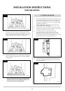
3. GAS SUPPLY
3.1 Before installation, ensure that the local distribution
conditions (identification of the type of gas and pressure)
and the adjustment of the appliance are compatible.
3.2 Ensure that the gas supply is capable of delivering the
required amount of gas and is in accordance with the rules
in force.
3.3 Soft copper tubing can be used to install the appliance. Soft
soldered joints can be used externally of the appliance.
3.4 The appliance is supplied complete with a factory fitted
isolation device incorporated into the inlet connection, no
further isolation device is required.
3.5 All supply gas pipes must be purged of any debris that may
have entered, prior to connection to the appliance.
3.6 The gas supply may enter through the floor directly under
the appliance or through the knockout panel in the rear RH
corner of the outer casing. In both instances, the front lower
panel is removable to aid connection of the gas supply and
a preformed pipe is factory fitted to make connection to the
main inlet isolation device easier.