


13
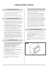
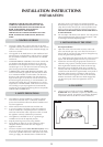
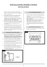
There is a cutout in the RH rear leg to enable a direct
straight connection to be made to the rear of the stove. See
diagram 3. A gas soundness check must be completed up to
the gas inlet connection.
4.5 Check the pull of the flue system by applying a lighted
smoke pellet to the flue system opening. If there is a
definite flow into the chimney, proceed with the
installation. If not, warm the chimney for a few minutes.
IF THERE IS STILL NO DEFINITE FLOW, THE FLUE MAY
REQUIRE ATTENTION - SEEK EXPERT ADVICE
4.6 The flue system may now be connected to the stove. Ensure
that all joints are sealed with a suitable fire resistant sealant.
It is also recommended that a physical retention method be
used at the flue spigot joint, self-tapping screws are
recommended..
4.7 Connect a suitable pressure gauge to the test point located
on the inlet fitting and turn on the gas supply. Light the
appliance and check all gas joints for gas soundness. Turn
the appliance to a maximum and check that the supply
pressure is as stated on the databadge. Turn the gas off and
replace the test point screw. Turn the gas on and check the
test point for gas soundness.
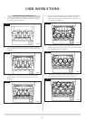
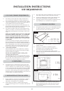
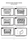
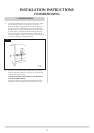
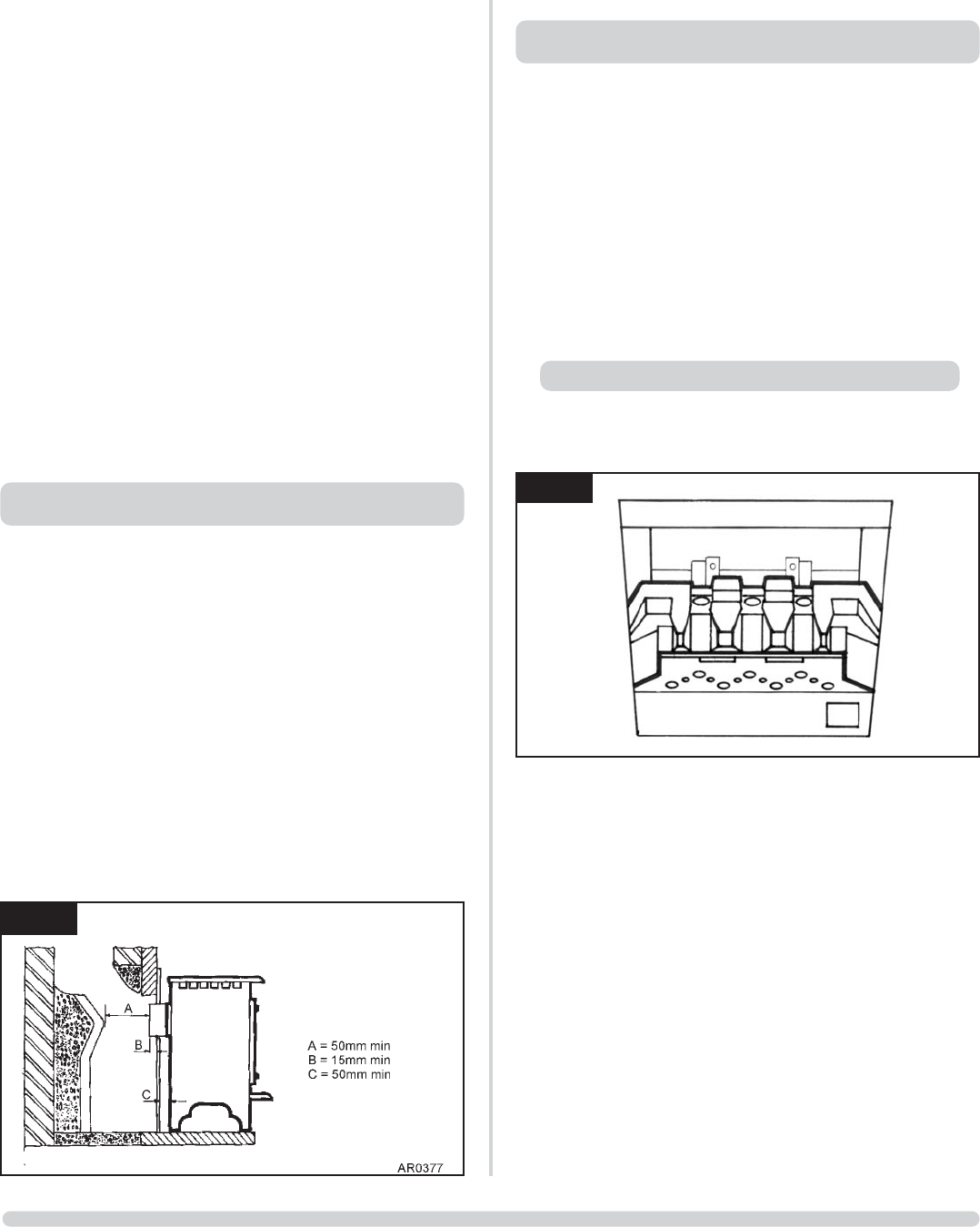
NOTE: The Small & Medium stoves are also suitable for
installation onto a fireplace opening. The following
method illustrates how this can be achieved with the aid
of the optional closure plate and spigot extension. Ensure
the fireplace dimensions are as shown in diagram 4.
5.8 Place the closure plate against the fireplace opening and
ensure there is sufficient overlap around the perimeter to
allow a fume tight seal to be made. Cut straight across the
top of the plate if trimming is required.
5.9 Seal the plate to the opening and the hearth with a suitable
heat resisting material. Ensure that any relief opening at the
bottom of the plate is left unobstructed.
5.10 Secure the spigot extension to the engine assembly and seal
with heat resisting tape or similar. Position the engine
assembly ensuring 50mm rear clearance is maintained and
then proceed with the installation as detailed in points 3.2
to 3.3 above. See diagram 4.
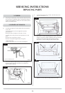
The major ceramic components can be found inside the
firebox. Remove the cast iron door using the tool provided
and remove all the protective packaging from these
components.
NOTE: THE CAST IRON IS HEAVY, TAKE EXTREME CARE
WHEN HANDLING.
Refer to ADVICE ON HANDLING AND DISPOSAL OF
FIRE CERAMICS in User Instructions section 5.
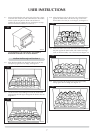
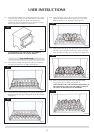
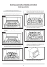
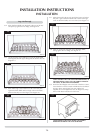
The loose coals should be arranged as specified in the
following steps. Care should be taken to ensure there is
sufficient space between the coals to allow flames to pass
through.
6.1 Place the flame baffle onto the burner and push up against
the rear tray lip, see diagram 5.
INSTALLATION INSTRUCTIONS
INSTALLATION
4
6. FUEL BED ARRANGEMENT
Small Marlborough and Stockton 6
5
AR0359
5. CLOSURE PLATE INSTALLATION