


20
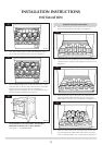
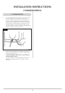
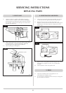
2.3 Loosen main injector nut on airbox and disconnect from
injector, see diagram 3, A.
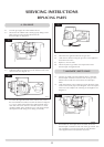
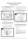
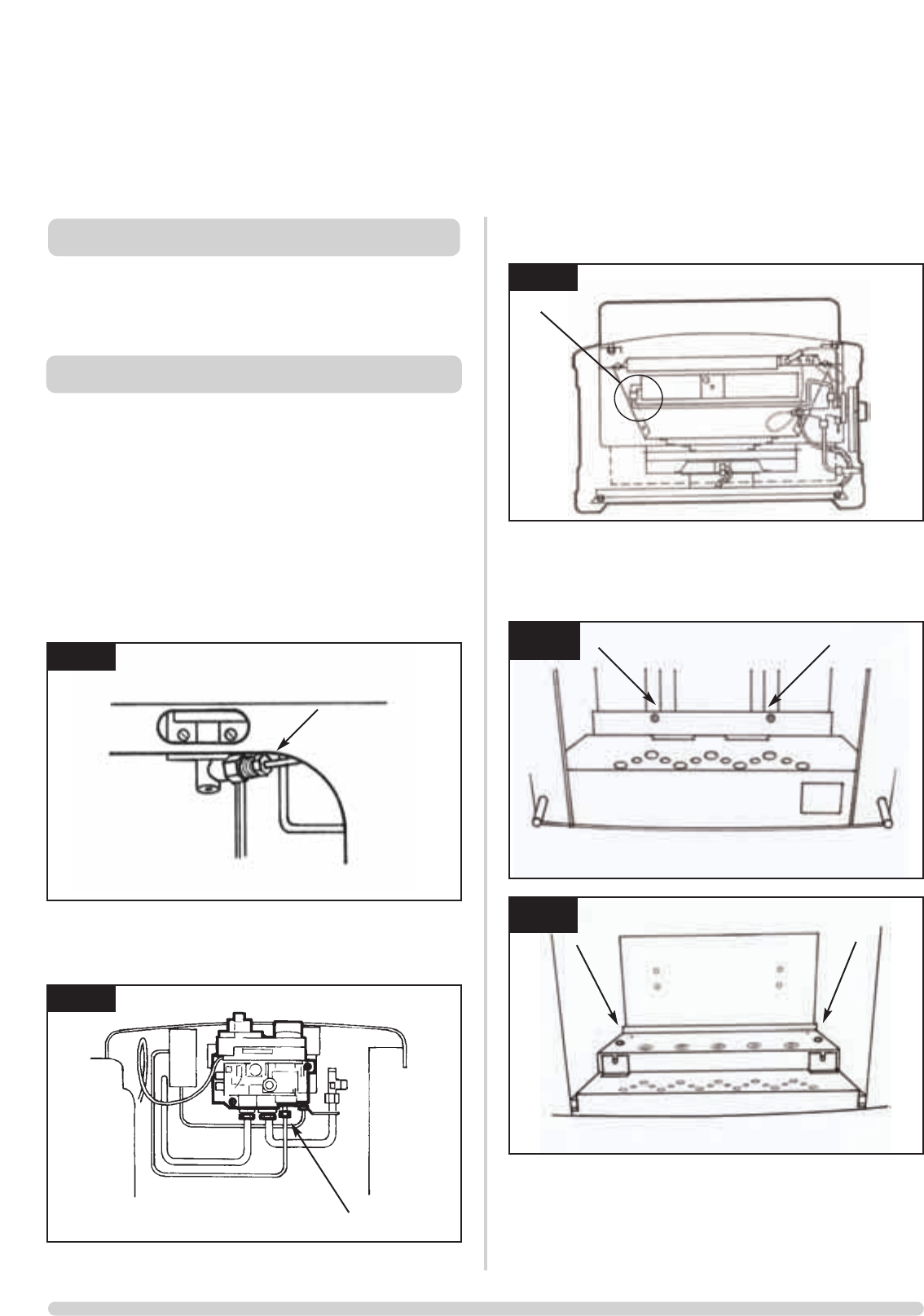
2.4 Remove the 2 screws attaching burner to back of unit, see
diagrams 4A & 4B. Carefully withdraw burner unit upwards
and tilt to remove the burner through door opening.
Remove the 2 screws holding the heat shield in place.
Replace in reverse order checking all joints for leaks.
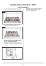
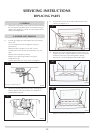
1.1 All principal components can be replaced without removing
the stove from its installation but it is essential that the gas
supply to the appliance is turned off at the isolation device
before proceeding further.
2.1 Turn the gas supply off at the isolation device. Ensure the
unit is cool.
Use cover material to front of appliance to protect
paintwork etc.
Remove the door and place to one side. (4 nuts).
Carefully remove the ceramic fuel components to a safe
place.
Remove front cover-plate (2 screws).
Remove cover plate fixing bracket (2 wing nuts).
(Small Stoves only)
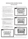
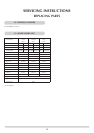
Unscrew pilot union nut on gas valve. See diagram 1.
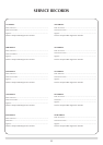
2.2 Disconnect thermocouple from gas valve. See diagram 2.
Remove ignition lead from electrode. (Cut cable tie to
ignition lead if required).
1. GENERAL
SERVICING INSTRUCTIONS
REPLACING PARTS
2. BURNER UNIT REMOVAL
1
2
3
4B
A
AR0391
AR0943
AR0389
AR0384
AR0385
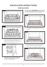
Viewing slot on Marlborough only
A
4A