


13
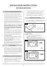
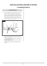
There is a cutout in the RH rear leg to enable a direct
straight connection to be made to the rear of the stove. See
diagram 3. A gas soundness check must be completed up to
the gas inlet connection.
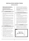
4.2 Check the pull of the flue system by applying a lighted
smoke pellet to the flue system opening. If there is a
definite flow into the chimney, proceed with the
installation. If not, warm the chimney for a few minutes.
IF THERE IS STILL NO DEFINITE FLOW, THE FLUE MAY
REQUIRE ATTENTION - SEEK EXPERT ADVICE
4.3 The flue system may now be connected to the stove. Ensure
that all joints are sealed with a suitable fire resistant sealant.
It is also recommended that a physical retention method be
used at the flue spigot joint, self-tapping screws are
recommended..
4.4 Connect a suitable pressure gauge to the test point located
on the inlet fitting and turn on the gas supply. Light the
appliance and check all gas joints for gas soundness. Turn
the appliance to a maximum and check that the supply
pressure is as stated on the databadge. Turn the gas off and
replace the test point screw. Turn the gas on and check the
test point for gas soundness.
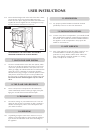
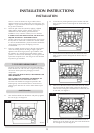
The major ceramic components can be found inside the
firebox. Remove the cast iron door using the tool provided
and remove all the protective packaging from these
components.
NOTE: THE CAST IRON IS HEAVY, TAKE EXTREME CARE
WHEN HANDLING.
Refer to ADVICE ON HANDLING AND DISPOSAL OF
FIRE CERAMICS in User Instructions section 5.
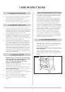
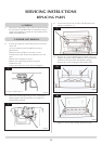
The loose coals should be arranged as specified in the
following steps. Care should be taken to ensure there is
sufficient space between the coals to allow flames to pass
through.
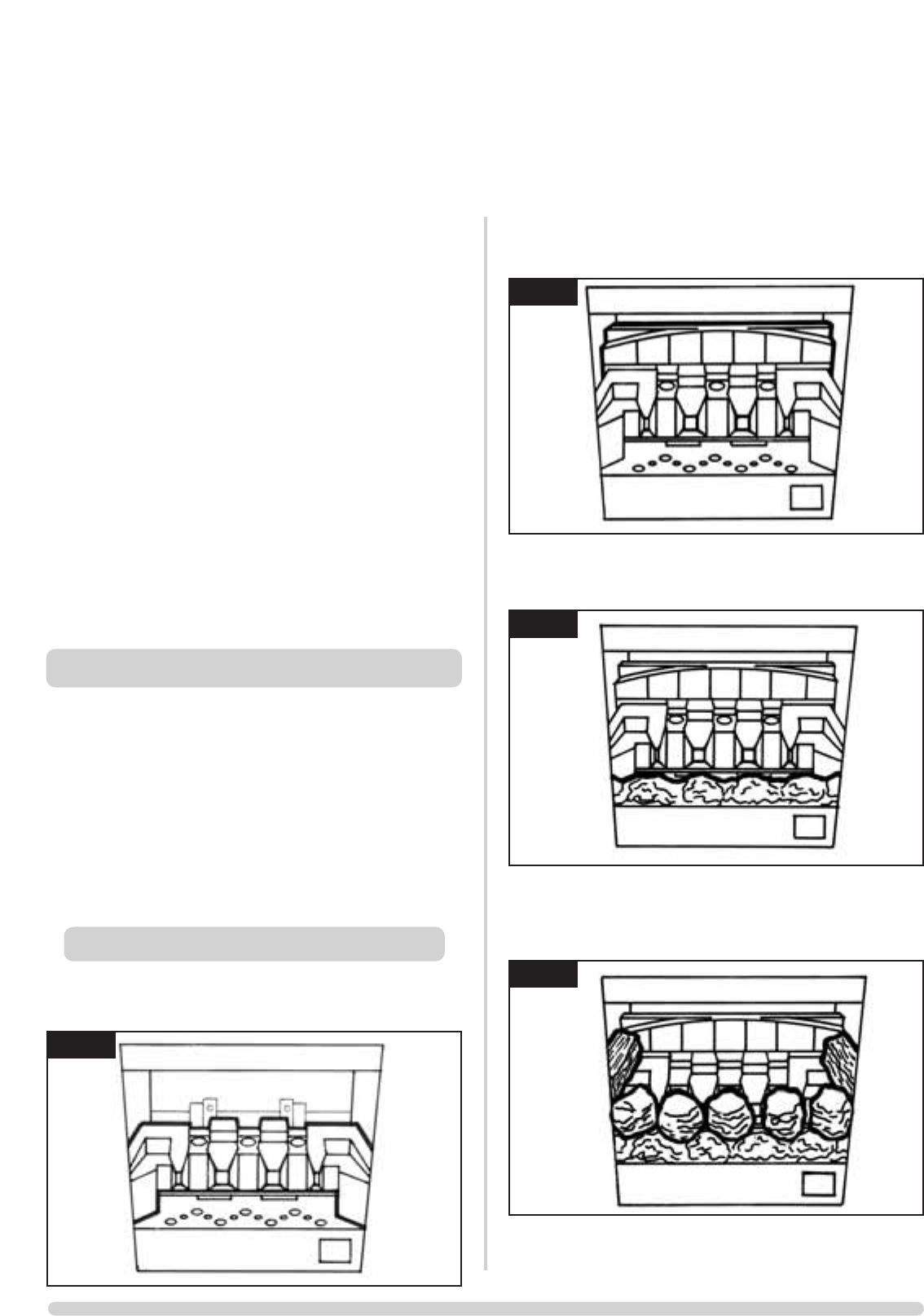
5.1 Place the flame baffle onto the burner and push up against
the rear tray lip, see diagram 4.
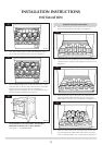
5.2 Locate the rear panel against the spacer brackets and slide
down so that it locates on the ledge of the flame baffle, see
diagram 5.
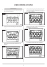
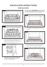
5.3 Locate the front coal between the heat shield and flame
baffle so that its ends sit flat against the burner skin, see
diagram 6.
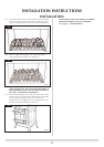
5.4 Place five of the loose round coals on the front coal so that
they lean against the flame baffle, in between the fingers.
Place the two rectangular coals behind the round coals, one
at each side, see diagram 7.
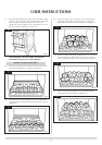
5.5 Place four of the loose round coals behind the first row so
that they sit on the fingers, the two outer coals should touch
the rectangular coals, see diagram 8.
INSTALLATION INSTRUCTIONS
INSTALLATION
5. FUEL BED ARRANGEMENT
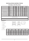
Small Clarendon
4
AR0359
5
AR0360
6
AR0361
7
AR0362