


11
AR0303
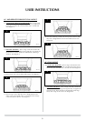
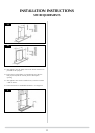
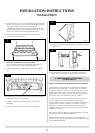
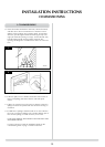
5.13 Fit the fret to the fire front using the two securing screws. See
Diagram 12.
12
AR0311
5.14 If the appliance is fitted with an alternative Gazco front
please refer to the separate leaflet supplied with the front.
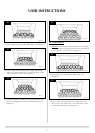
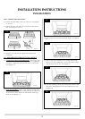
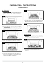
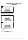
6. ARRANGEMENT OF FUELBED
COMPONENTS
ADVICE ON HANDLING AND DISPOSAL OF FIRE CERAMICS
The fuel effect and side panels in this appliance are made from
Refractory Ceramic Fibre (RCF), a material which is commonly
used for this application. Protective clothing is not required when
handling these articles, but we recommend you follow normal
hygiene rules of not smoking, eating or drinking in the work area
and always wash your hands before eating or drinking.
To ensure that the release of RCF fibres are kept to a minimum,
during installation and servicing a HEPA filtered vacuum is
recommended to remove any dust accumulated in and around the
appliance before and after working on it. When servicing the
appliance it is recommended that the replaced items are not
broken up, but are sealed within heavy duty polythene bags and
labelled as RCF waste.
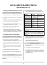
RCF waste is classed as stable, non-reactive hazardous waste and
may be disposed of at a licensed landfill site.
Excessive exposure to these materials may cause temporary
irritation to eyes, skin and respiratory tract; wash hands thoroughly
after handling the material.
14
INSTALLATION INSTRUCTIONS
INSTALLATION
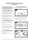
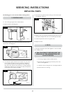
5.6 Carefully fit the convector box, feeding the piping through into
the box. Secure the box to the wall, through the flange or base
ensuring that the box is square in the opening. Any
undulations or gaps between the convector box and the wall
should be filled with a non-combustible material. Do not use
silicone as it makes future removal almost impossible.
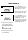
5.7 Refit the fire assembly and front air guide back into the
convector box. See Diagram 9.
AR0314
9
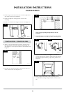
5.8 HAVE YOU PURGED THE GAS SUPPLY PIPES.
This is essential to expel any foreign matter that might get
blown into the valve assembly causing blockages.
5.9 Connect the 8mm gas supply pipe to the fire. See Diagram
10.
10
AR0944
5.10 Check the gas connections to the fire are sound. Light the fire
and check all joints on the appliance.
5.11 Check the appliance working pressure is correct. See
databadge.
5.12 Fit the fire trim to the convector box. See Diagram 11.