


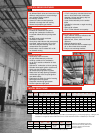
COMBUSTION AIR AND VENTILATION
Combustion air and venting requirements for all gas-fired heating equipment must be provided per the National Fuel Gas Code NFPA54 or the authority having jurisdiction over the
installation. In contaminated atmospheres or high humidity areas, optional outside air for combustion can be supplied. Heaters can be common vented, direct vented, or indirect
vented. Refer to the Installation and Operation Instructions for further information. A vented installation must be vented to the outside of the building with a flue pipe. An Indirect
vented installation requires a minimum ventilation flow of 4 CFM per 1000 Btu/hr of total installed heater capacity on natural gas by either gravity or power ventilation (4.18 CFM per
1000 Btu/hr on propane). For indirect vented applications, building exhaust openings must be located above the level of the heaters and inlet air openings must be located below
the level of the heaters.
FOR YOUR SAFETY
OPERATE SPACE-RAY GAS INFRARED HEATERS WITH PROPER CARE AND OBSERVE ALL SAFETY PRECAUTIONS. Installation and service must be performed by a licensed con-
tractor. The installation must conform to local codes. In the absence of local codes, the installation must conform to the National Fuel Gas Code ANSI Z223.1 (latest edition, also known
as NPFA54) or CAN / CSA-B149 installation codes (latest edition). These codes are available from the National Fire Protection Association, Inc., Batterymarch Park, Quincy, MA 02269
or the Canadian Gas Association, 55 Scarsdale Road, Toronto, Ontario MB3 2R3 Canada.
A Division of Gas-Fired Products, Inc.
P.O. Box 36485 Charlotte, NC 28236 Telephone (Toll Free) 1-800-438-4936 (704) 372-3485 Fax (704) 332-5843
Copyright 2003, GFP INC. 10325M FORM#S45504
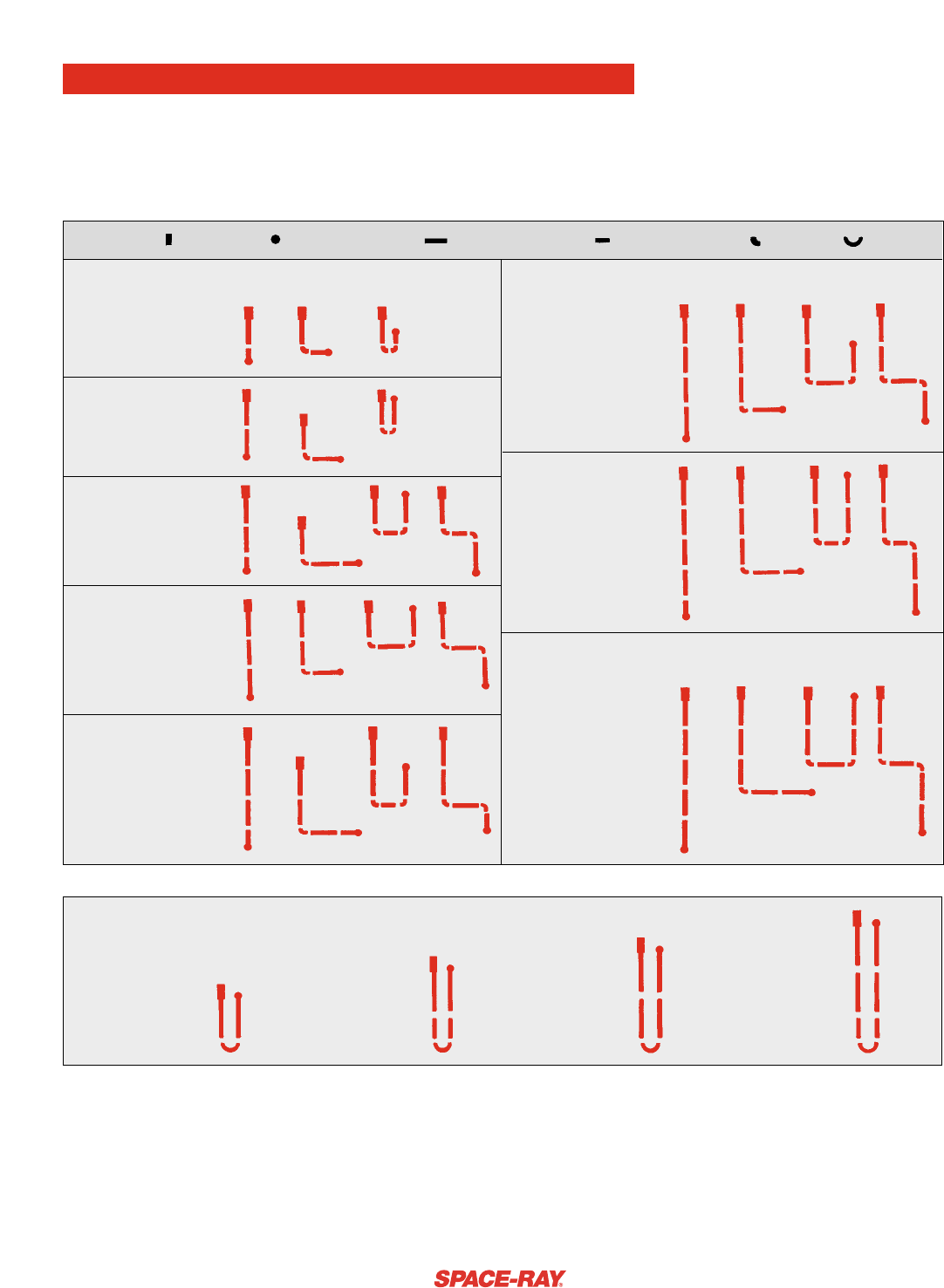
ETS/ETU SERIES LAYOUTS
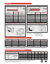
The ETS/ETU series, with more than 100 different configurations, offers optimum flexibility in custom designing an
infrared heating system. The ETS series is available in multiple configurations (straight, L, Z, and expanded U-shape) with
lengths from 15’ to 80’ long. For added versitality, 90° elbows, corner reflectors, and side reflectors are available for close
area mounting near walls, doors, and corners. The ETU series is available in seven different configurations and provides
more uniform radiant heat energy distribution. The ETU series is ideal for high heat loss areas and spot heating.
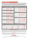
ETS/ETU SERIES LAYOUTS
Only 15 ft. to 50 ft. systems are shown. Please refer to the Installation and Operation Instructions for complete layouts.
www.spaceray.com • email: info@spaceray.com
LEGEND
CONTROL UNIT DRAFT INDUCER 10FT. BODY SECTION 5 FT. BODY SECTION 90° ELBOW 180° U BEND
ETS SERIES
STRAIGHT L-SHAPE
EXPANDED
Z-SHAPE STRAIGHT L-SHAPE
EXPANDED
Z-SHAPE
U-SHAPE U-SHAPE
15 FT SYSTEM
40 FT SYSTEM
20 FT SYSTEM
25 FT SYSTEM
45 FT SYSTEM
30 FT SYSTEM
35 FT SYSTEM 50 FT SYSTEM
ETU SERIES
20 FT SYSTEM 30 FT SYSTEM 40 FT SYSTEM 50 FT SYSTEM