


MODEL
ETS AND ETU
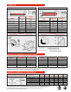
DRAFT INDUCER CONTROL BOX
Flue Connection: 4” Round for ETS/U (40-75)
6” Round for ETS/U (80-250)
Fresh Air Connection: 4” Round for ETS/U (40-75)
6” Round for ETS/U (80-250)
ETS OPTIONS
90° ELBOW CORNER REFLECTOR
ETS - BOTTOM VIEW ETS - END VIEW
DIMENSIONS
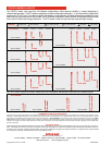
MINIMUM RECOMMENDED MOUNTING HEIGHTS
MINIMUM CLEARANCES TO COMBUSTIBLES
ETU - BOTTOM VIEW ETU - END VIEW
TOTAL TUBE OVERALL
LENGTH (FT) DIMENSION”L”(FT)
D
E
S
I
G
N
C
E
R
T
I
F
I
E
D
TOTAL TUBE OVERALL
LENGTH (FT) DIMENSION ”L” (FT) MODEL
ETS (40, 50)
ETS (40, 50, 60, 75)
ETS (40, 50, 60, 75, 80, 90,
100, 110, 120, 130)
ETS (80, 90, 100, 110, 120,
125, 130, 140, 150,160,175)
ETS (125, 130, 140, 150,
160,175, 180, 200, 225, 250)
ETS (180, 200, 225, 250)
ETS (180, 200, 225, 250)
ETS (180, 200, 225, 250)
15’
20’
30’
40’
50’
60’
70’
80’
17’3”
22’3”
32’3”
42’3”
52’3”
62’3”
72’3”
82’3”
ETU (40, 50, 60, 75)
ETU (50, 60, 75, 80, 90,
100, 110, 120, 130)
ETU (80, 90, 100, 110, 120,
125,130, 140, 150, 160, 175)
ETU (125, 130, 140, 150,
160,175,180, 200,225, 250)
ETU (180, 200, 225, 250)
ETU (180, 200, 225, 250)
ETU (180, 200, 225, 250)
MODEL
MODEL
ETS/U 40
ETS/U 50
ETS/U 60
ETS/U 75
ETS/U 80 & 90
ETS/U 100 & 110
10 feet
11 feet
12 feet
13 feet
13 feet
14 feet
9 feet
10 feet
11 feet
12 feet
12 feet
13 feet
ETS/U 120 & 125
ETS/U 130 & 140
ETS/U 150
ETS/U 160 & 175
ETS/U 180 & 200
ETS/U 225 & 250
14 feet
15 feet
15 feet
16 feet
18 feet
20 feet
13 feet
14 feet
14 feet
15 feet
17 feet
19 feet
HEIGHT AT
HORIZONTAL
HEIGHT AT
45° ANGLE
ETS/U (40, 50)
ETS/U (60, 75)
ETS/U (80, 90)
ETS/U 100
ETS/U (110, 120, 125, 130)
ETS/U (140, 150, 160, 175)
ETS/U (180, 200, 225, 250)
MINIMUM CLEARANCES TO COMBUSTIBLES MODEL NO.
SIDE
CEILING BELOW END
(45°)
FRONT
(45°)
REAR
HORIZONTAL
27”
27”
52”
66”
66”
84”
86”
6”
6”
6”
6”
6”
6”
18”
40”
60”
84”
88”
101”
106”
132”**
30”
30”
30”
40”
40”
48”
48”
48”
48”
52”
66”
66”
84”
84”
12”
12”
12”
20”
20”
24”
24”
*When used indirect vented, clearances to ceiling from top of exhaust hood must be 12” on ETS/U (40-75), and 18” on
ETS/U (80-250). If optional corner or U-bend reflectors are not used, clearance must be 18”. **Clearance below the heater
is 132” for the first 20 ft. of the emitter tube and reduces to 72” 20 ft. downstream from the control box.
Note: Consult factory if reduced clearances are required.
This chart is intended as a guide only, as heaters may be mounted at various heights and angles. Since straight tube heaters are always hotter at the burner end than
at the exhaust end, always observe the minimum recommended mounting heights shown above. Use ETU series for spot heating. Please consult your local Space-
Ray Representative for a detailed analysis of your particular infrared heating requirements.
20’
30’
40’
50’
60’
70’
80’
12’9”
17’9”
22’9”
27’9”
32’9”
37’9”
42’9”
L
L
18”
18”
9”
13”
6”
15”
Control
Box
Draft
Inducer
18”
31”
6”
45° ANGLE
(MAXIMUM)
HEIGHT AT
HORIZONTAL
HEIGHT AT
45° ANGLE
1/ 2