En-12
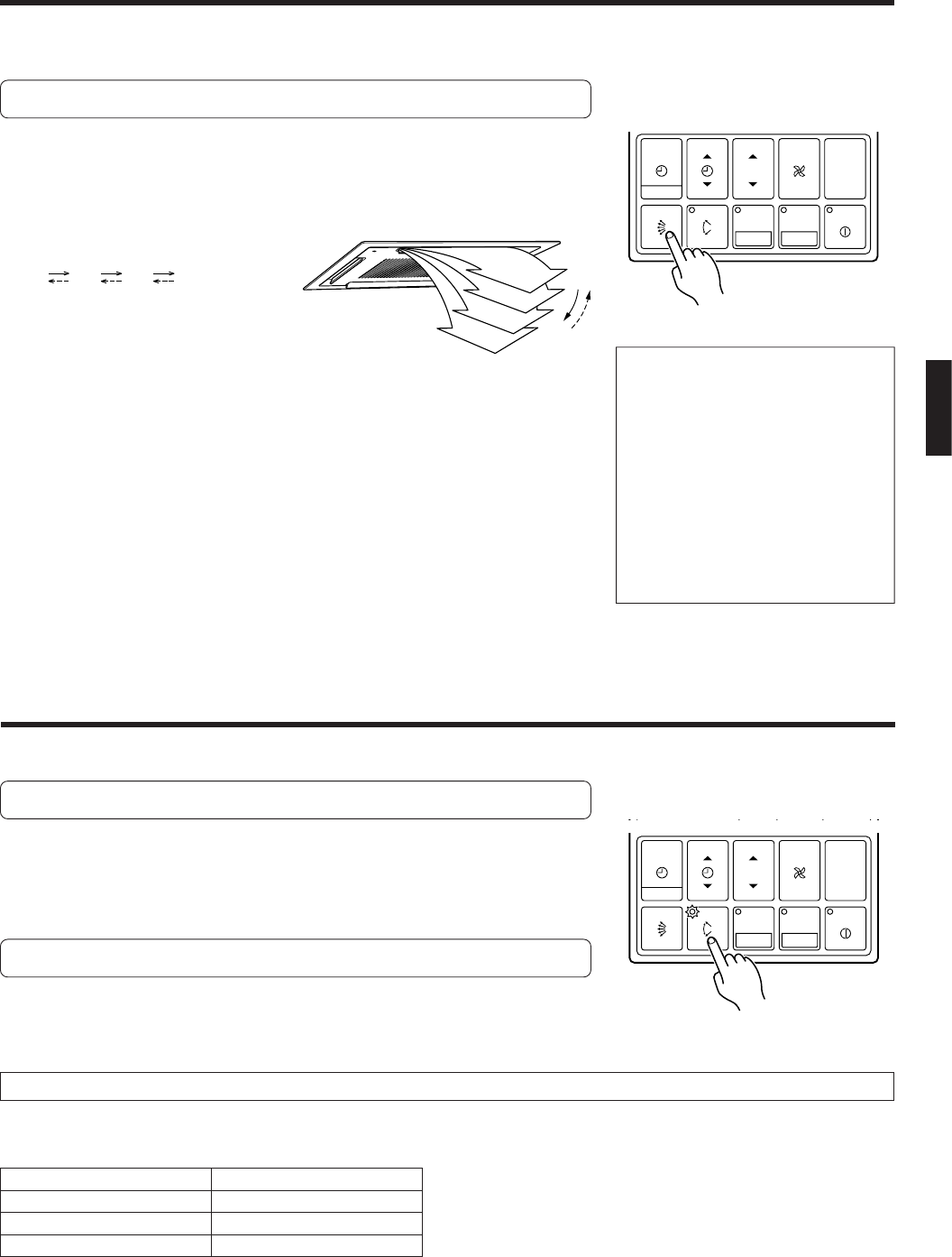
Vertical Air Flow Direction Adjustment
Press the AIR FLOW DIRECTION SET button.
Each time the button is pressed, the air flow direction range will change as fol-
lows:
1
2 3 4
The remote controller’s display does not change.
● Use the air flow direction adjustments within the ranges shown above.
● The air flow direction is set automatically as shown, in accordance with the
type of operation selected.
During Cooling mode : Horizontal flow 1
* During Heating mode : Downward flow 4
● During AUTO mode operation, for the first minute after beginning operation,
air flow will be horizontal 1; the air flow direction cannot be adjusted during
this period.
ADJUSTING THE DIRECTION OF AIR CIRCULATION
Instructions relating to heating (*) are applicable only to “HEAT & COOL MODEL” (Reverse Cycle).
Begin air conditioner operation before performing this procedure.
● Always use the remote controller’s AIR
FLOW DIRECTION SET button to ad-
just the UP/DOWN air flow direction
flaps. Attempting to move them manu-
ally could result in improper operation;
in this case, stop operation and restart.
The flaps should begin to operate
properly again.
● When used in a room with infants, chil-
dren, elderly or sick persons, the air
flow direction and room temperature
should be considered carefully when
making settings.
Begin air conditioner operation before performing this procedure.
To Select SWING Operation
Press the AIR FLOW DIRECTION SWING button.
The AIR FLOW DIRECTION SWING lamp (orange) will light.
In this mode, the UP/DOWN air flow direction flaps will swing automatically to
direct the air flow both up and down.
To Stop SWING Operation
Press the AIR FLOW DIRECTION SWING button once again.
The AIR FLOW DIRECTION SWING lamp will go out.
Air flow direction will return to the setting before swing was begun.
● The range of swing is relative to the currently set air flow
direction.
Air flow direction range (see Fig. 6)
● If the swing range is not as desired, use the remote con-
troller’s AIR FLOW DIRECTION SET button to change the
range of swing.
● The SWING operation may stop temporarily when the air
conditioner’s fan is not operating, or when operating at
very low speeds.
About Swing Operation
Air flow direction set
1
2, 3
4
Range of swing
1 to 3
2 to 4
1 to 4 (All range)
SWING OPERATION
TIMER
MODE
SET
ZONE
START/STOP
CLOCK ADJUST
SET TIME TEMP./DAY FAN
CONTROL
MASTER
CONTROL
DAY OFF
ENERGY SAVE
Fig. 6
TIMER
MODE
SET
ZONE
START/STOP
CLOCK ADJUST
SET TIME TEMP./DAY FAN
CONTROL
MASTER
CONTROL
DAY OFF
ENERGY SAVE
1
2
3
4
