


11
920-198-00
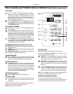
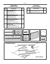
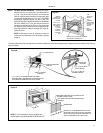
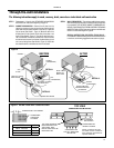
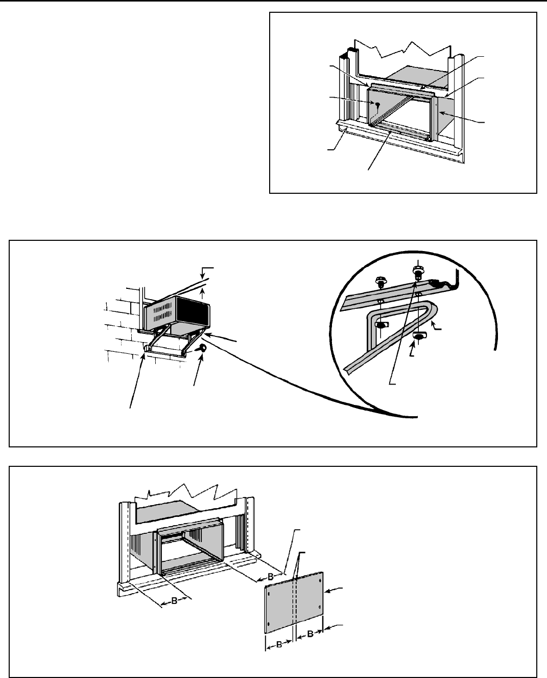
Figure D
⅜" DOWN SLOPE
SUPPORT BRACK ET
(ITEM #1)
#12A x 2" SCREW
(ITEM #4)
1" x 4" OR 2" x 4" SPACER SHOULD BE USED
BE TWEEN WALL AND BRACKET WHEN IN STALLED
ON ALUMINUM, ASBESTOS OR VINYL SIDING
SUPPORT
BRACKET
10 – 24 FLAT WELD
NUT (ITEM #3)
10 – 24 x 1" HEX HD.
SCREW (ITEM #2)
STEP 8 OUTSIDE SUPPORT MOUNTING – Assemble the support
brackets (Item #1) to the bottom rails of the cab i net with four
(4) 10-24 1" long screws (Item #2) and four (4) 10-24 fl at nuts
(Item #3). Adjust the support brackets to bring the bottom pads
in contact with the wall surface. (A 1" x 4" or 2" x 4" SPACER
SHOULD BE USED BETWEEN THE WALL AND THE
SUPPORT BRACKETS WHEN IN STALLED ON ALU MI NUM
OR VINYL SIDING). Drill
5
⁄
32
" dia. pilot holes and secure the
brack ets to the wall with two (2) #12A x 2" long screws (Item
#4). Adjust the support brackets to provide an ap prox i mate 3/8"
down slope toward the out side for drainage. (See Figure D).
Tighten all screws.
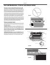
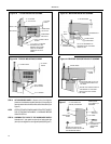
NOTE: The discharge air, return air, condenser air inlets and
outlets must be unobstructed to avoid recirculation of rejected
heated air.
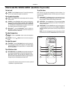
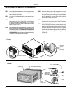
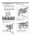
The following illustrations show a standard frame con struc tion installation as well as some suggested ways of adapt ing the support bracket to thick walls and
large stone ledges.
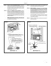
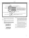
CENTER
CABINET IN
WINDOW SIDE
TO SIDE.
DRILL (3)
5
⁄
32
"
PILOT HOLES
AND INSTALL
(3) #12A x
2" LONG
SCREWS
(ITEM #4)
WINDOW
SILL
LOCATE SILL PLATE GUIDE CHAN NEL
JUST BACK OF WIN DOW SILL
TOP
SUPPORT
ANGLE
PULL
WINDOW
SASH DOWN
BEHIND TOP
SUPPORT
ANGLE
SIDE
SUPPORT
ANGLE
Figure C
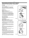
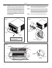
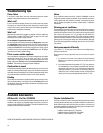
Figure E
MEASURE DISTANCE "B" TO INSIDE OF THE
CHANNEL ON EACH SIDE
CUT HERE AND DISCARD CENTER WASTE
MATERIAL.
WINGBOARD
SUBTRACT ⅛" FROM DIMENSION "B" AND
MEA SURE FROM THE EDGE OF THE WING-
BOARD (ITEM # 8), MARK, SCORE AND CUT
WITH APPROPPRIATE CUTTING TOOL
NOTE: It is not necessary to cut the wingboard for
vertical height; only horizontal WIDTH Dimension “B”.