10
920-198-00
Standard Sash Window Installations
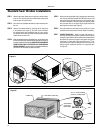
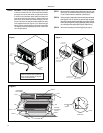
STEP 1 Remove decorative plastic return air grille to a safe area away
from unit. The return air grille can be removed by pulling at the
sides on either the top or bottom.
STEP 2 Also remove the installation hardware to a safe area away from
the unit.
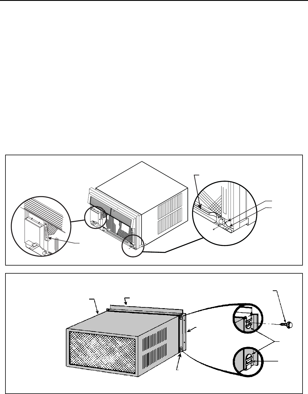
STEP 3 Remove the chassis retainer by re mov ing the far right screw
in the basepan (see Figure A); save this screw to reattach
the chassis retainer after installation (Step 15). Also, remove
and discard the two retainer screws and black plastic washers
located at the rear of the unit.
STEP 4 While an assistant holds the cabinet sta tion ary, use the hand pull at
the front of the base pan, together with the pull strap (see Figure A)
to pull the chassis out of the cabinet. REMOVE THE LARGE WHITE
FOAM BLOCKS USED TO RESTRAIN THE COM PRES SOR
DURING SHIPMENT. Inspect basepan for dislodged white blocks,
and remove. Do not remove any other foam parts.
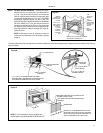
STEP 5 Anchor the side angles (Item #6) by engaging the tabs at each
end of the sill plate (see Figure B) with the bottom loops of the
side angle. Engage the tabs at each end of the top angle (Item
#5) with the top loops of the side angle (see Figure B). Install
two (2) screws (Item #7) to secure the top angle tabs and the
side angle to the cabinet (see Figure B).
STEP 6 Check the window sill and frame to be sure they are in good
condition and fi rmly anchored to the wall. Repair if necessary.
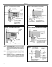
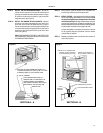
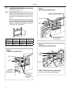
STEP 7 CABINET MOUNTING – Raise the lower sash window ¼"
more than the height of the cabinet. Carefully slide the cabinet
through the open window until the sill plate channel rests behind
the window sill and the top support rests against the window
(see Figure C.) Center side to side and drill three (3)
5
⁄
32
" dia.
pilot holes into the window sill using the holes in the cabinet sill
plate as a guide. Install three (3) #12A x 2" long screws (Item
#4, Figure C).
HAND PULL
FAR RIGHT
SCREW
CHASSIS
RETAINER
WIRE
PULL STRAP
Figure A
Figure B
CABINET
TOP ANGLE (ITEM #5)
SIDE ANGLE
(ITEM #6) 2
REQUIRED
8A x ⅜" LONG SCREW
(ITEM #7) 2 REQUIRED
TAB
LOOP
SILL
PLATE TAB
DETAIL B-1
DETAIL B-2


