


8
920-197-00
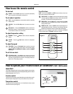
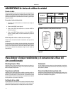
STEP 6 Inspect the unit before inserting it into the sleeve. The fan and
blower wheel should be manually rotated to insure that they turn
freely. Be sure the electrical cord will be out of the way when
inserting the unit into the sleeve.
NOTE: For your safety, DO NOT plug the electrical cord into an
electrical outlet until installation is complete.
STEP 7 If the unit checks out OK, it is ready to be placed into position on
bottom rails of the cabinet and pushed into place.
NOTE: Do all lifting of the unit by the bottom pan only and with
assistance or help as necessary (see Figure A).
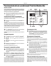
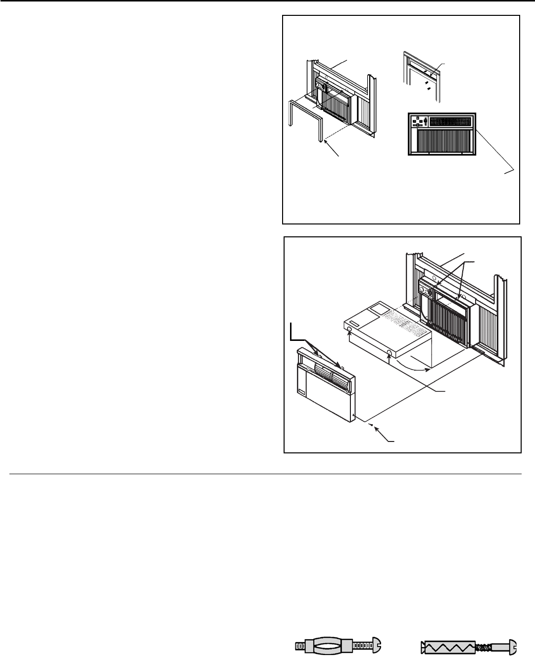
STEP 8 Install the white chassis seal gasket (item #6, page 6) and the
gray window seal gasket (item #5). Carefully insert the white
gasket (item #6) between the chassis and the cabinet starting at
either bottom corner and go up the side, across the top and down
the opposite side. Insert the gray gasket (item #5) between the
window sashes as shown in Figure D. If chassis seal gasket is
not installed, the operation of the unit will be negatively affected.
Also, the operation noise and outside noise will be amplifi ed.
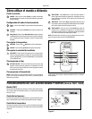
STEP 9 Hold the decorative front as shown in Figure E. Insert the two
tabs of the Decorative Front Panel into the slots in the top of the
cabinet and lower the bottom of the decorative front to the bottom
of the cabinet. Route the electrical cord to the right or left side
of the bottom of the cabinet as required by the location of the
electrical wall outlet. Use the notches provided at the bottom of
the Decorative Front Panel for routing the electrical cord out of
the unit. Attach the decorative front to the cabinet with two (2)
No. 8 x ½" Phillips head screws (item #2, page 6).
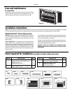
STEP 10 CIRCUIT PROTECTION - If the air conditioner is circuit protected by a
fuse, use a "TIME DELAY" fuse or HACR type Circuit Breaker due to
momentary high current demand when your air conditioner is started.
Before operating your unit, verify the ampere rating of the time-delay
fuse or circuit breaker which protects your unit. The ampere rating
of the time-delay fuse or circuit breaker shall be 15 amps. Refer to
Operation section for more detailed operating instructions.
Figure D
TO PREVENT AIR LEAKS AROUND
THE AIR CONDITIONER, INSERT
THE WHITE FOAM GASKET (item
# 6, page 6) BETWEEN THE AIR
CONDITIONER AND THE CABINET.
CHASSIS SEAL
GASKET
GRAY FOAM
GASKET
(see illustration,
item #5 on page 6)
SCREW, #8 x ½" PHILLIPS HEAD
(See ilustration, item # 2, page 6)
2 REQUIRED (1 EACH SIDE)
TAB SLOTS
NOTCHES PROVIDED
FOR ELECTRICAL
CORD EXIT
TAB
LOCATIONS
Figure E
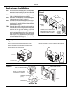
STEP 1 After removing the unit from shipping carton, remove tape holding
decorative front in place. Lay front in a safe out-of-the-way place,
then slide chassis out of cabinet (see Figure A, page 7).
STEP 2 Remove the shell channel from the top of the cabinet (see Figure
B, page 7).
NOTE: Not applicable to heat pump models sold without quick
mounting cabinet.
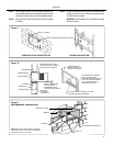
STEP 3 LAYOUT - Cut and frame in an opening in the desired wall area
using the illustration as a guide (see Figure F).
STEP 4 Place the cabinet in the framed opening.
NOTE: Measure and shim void spaces between the side of
cabinet and wood framing before securing to wall.
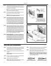
EXPANSION ANCHOR BOLT
MOLLY OR TOGGLE BOLT
STEP 5 Position the front edge to extend into the room 3/4" minimum at
top of cabinet and 1" minimum at bottom (see Figure G).
STEP 6 Secure each side of the cabinet with No. 8 x ⅞" hex head screws
(item #3, page 6) or nails through the holes in the sides.
NOTE: ALTERNATE FASTENERS WHICH MAY BE USED FOR
SECURING THE UNIT CABINET TO A WALL, INCLUDING
MASONRY WALLS, ARE NOT FURNISHED (AVAILABLE AT
LOCAL HARDWARE STORES).
Thru-the-wall installations