


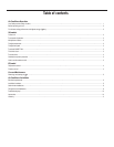
8
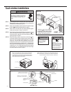
STEP 1 Afterremovingtheunitfromshippingcarton,removetapeholding
decorativefrontinplace.Layfrontinasafeout-of-the-wayplace,
then slide chassis out of cabinet (seeFigure A, page7).
STEP 2 Removetheshellchannelfromthetopofthecabinet(seeFigure
B, page7).
NOTE: Not applicable to heat pump models sold without quick
mountingcabinet.
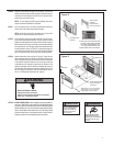
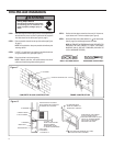
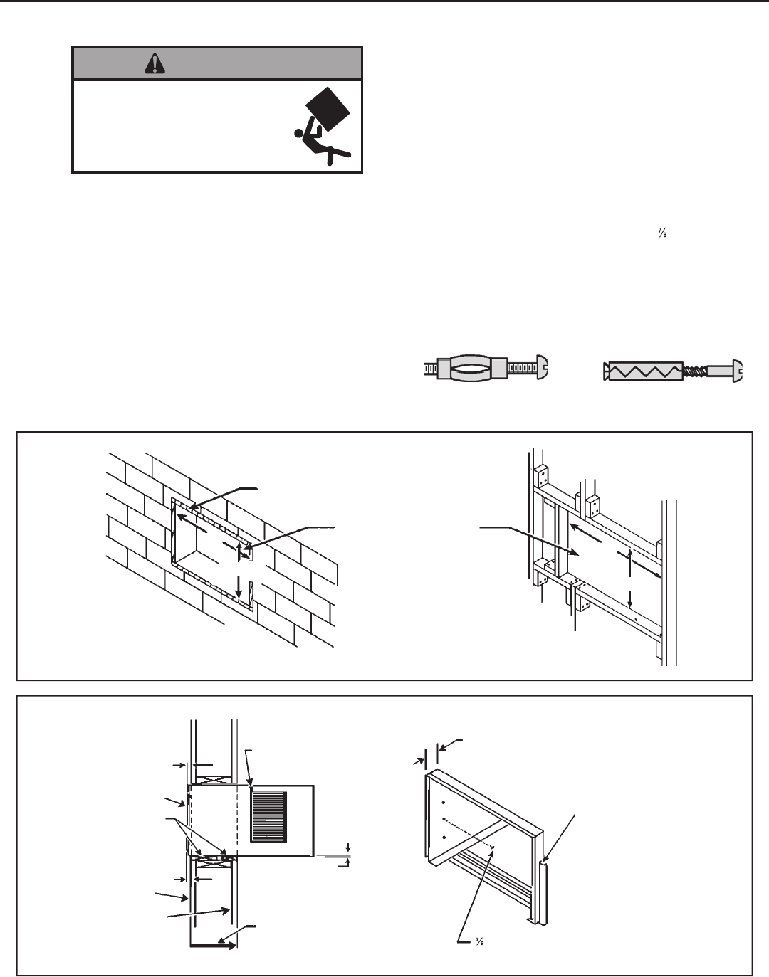
STEP 3 LAYOUT - Cut and frame in an opening in the desired wall area
usingthe illustration as aguide (see Figure F).
STEP 4 Place the cabinet in the framedopening.
NOTE: Measure and shim void spaces between the side of
cabinet and woodframing before securingto wall.
EXPANSION ANCHOR BOLT
MOLLYOR TOGGLEBOLT
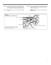
STEP 5 Position thefront edge to extend into theroom 3/4"minimum at
top of cabinet and1" minimumat bottom (see Figure G).
STEP6 Secure each side of the cabinet with No. 8 x
" hex head screws
(item#3,page6)ornailsthroughtheholesinthesides.
NOTE:ALTERNATEFASTENERSWHICHMAYBEUSEDFOR
SECURING THE UNIT CABINET TO A WALL, INCLUDING
MASONRY WALLS, ARE NOT FURNISHED (AVAILABLE AT
LOCAL HARDWARE STORES).
Thru-the-wall installations
Falling Object Hazard
Not following Installation Instructions
for mounting your air conditioner can
result in property damage, injury, or
death.
WARNING
Figure F
FINISHED OPENING SIZE
2" x8"FRAME
20"
14¼"
14¼"
20"
CONCRETE BLOCK CONSTRUCTION FRAME CONSTRUCTION
Figure G
¾"MINIMUM
CABINET FRONT
1"THICKLUMBER
1"MINIMUM
INSIDEWALL
EXTERIORWALL
TRIM AROUNDTHE CABINET
WITHA SUITABLEWOOD
MOULDINGAND FINISH TOSUIT.
CAULKALL AROUNDCABINET
ONOUTSIDE TOINSUREA
WEATHERTIGHT SEAL.
¼"SLOPE
DOWN.POSITION AND
SECURECABINET
DOWNWARD. SLOPE
OUTSIDE FORDRAINAGE.
MAX. WALL
THICKNESS
ALLOWED 8½"
FRONTEDGE OFLOUVERS
MUSTALWAYS BEOUTSIDEOF
EXTERIORWALLSURFACE
¾"MINIMUM FRONT
EDGEOF CABINETTO
INSIDEWALL SURFACE.
"SLOTTEDHEAD SCREWS(3EA. SIDE)
NAILSMAY BEUSEDIF DESIRED.