


Heating Element
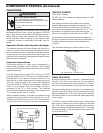
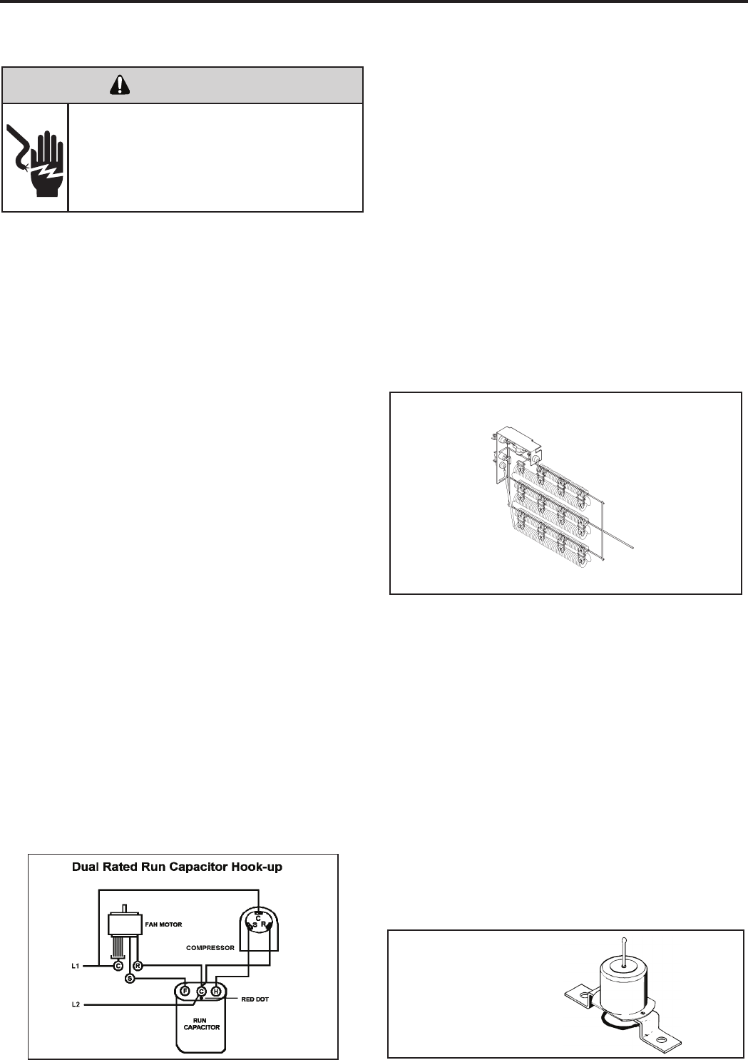
HEATING ELEMENT
(“WE” &”WY” Models)
All “WE” and “WY” models are equipped with a 3.3 KW
heating element.
The heating element has two heater limit switches
(bimetal thermostats) connected in series with it. The
Primary limit located near the bottom, will open the
circuit when the temperature reaches 130°F +/-5°. The
Secondary is a high limit switch near the top of the
element. It is designed to open the circuit at 165°F +/-8°.
Should the fan motor fail or filter become clogged etc.,
the high limit switch will open and interrupt the power to
the heater before reaching an unsafe temperature
condition.
Test the heater element for continuity below 130°F.
Not actual element - for reference only
14
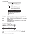
CAPACITORS
ELECTRIC SHOCK HAZARD
WARNING
Turn off electric power before servicing.
Discharge capacitor with a 20,000 Ohm 2 Watt
resistor before handling.
Failure to do so may result in personal injury,
or death.
Many motor capacitors are internally fused. Shorting the
terminals will blow the fuse, ruining the capacitor. A 20,000
ohm 2 watt resistor can be used to discharge capacitors
safely. Remove wires from capacitor and place resistor
across terminals. When checking a dual capacitor with
a capacitor analyzer or ohmmeter, both sides must be
tested.
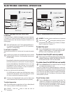
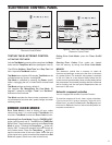
Capacitor Check with Capacitor Analyzer
The capacitor analyzer will show whether the capacitor is
“open” or “shorted.” It will tell whether the capacitor is within
its micro farads rating and it will show whether the capacitor
is operating at the proper power-factor percentage. The
instrument will automatically discharge the capacitor when
the test switch is released.
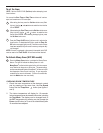
Capacitor Connections
The starting winding of a motor can be damaged by a
shorted and grounded running capacitor. This damage
usually can be avoided by proper connection of the running
capacitor terminals.
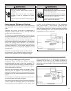
From the supply line on a typical 230 volt circuit, a 115 volt
potential exists from the “R” terminal to ground through a
possible short in the capacitor. However, from the “S” or
start terminal, a much higher potential, possibly as high as
400 volts, exists because of the counter EMF generated
in the start winding. Therefore, the possibility of capacitor
failure is much greater when the identied terminal is
connected to the “S” or start terminal. The identied
terminal should always be connected to the supply line, or
“R” terminal, never to the “S” terminal.
When connected properly, a shorted or grounded running
capacitor will result in a direct short to ground from the “R”
terminal and will blow the line fuse. The motor protector
will protect the main winding from excessive temperature.
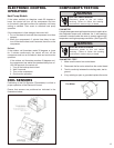
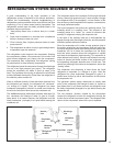
DRAIN PAN VALVE
During the cooling mode of operation, condensate which
collects in the drain pan is picked up by the condenser
fan blade and sprayed onto the condenser coil. This as-
sists in cooling the refrigerant plus evaporating the water.
During the heating mode of operation, it is necessary that
water be removed to prevent it from freezing during cold
outside temperatures. This could cause the condenser
fan blade to freeze in the accumulated water and prevent
it from turning.
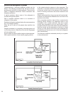
To provide a means of draining this water, a bellows type
drain valve is installed over a drain opening in the base
pan. This valve is temperature sensitive and will open
when the outside temperature reaches 40°F. The valve
will close gradually as the temperature rises above 40°F
to fully close at 60°F.
Drain Pan Valve
COMPONENTS TESTING (Continued)