16
920-024-05 (12-04)
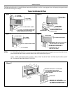
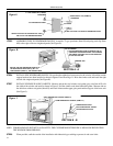
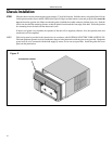
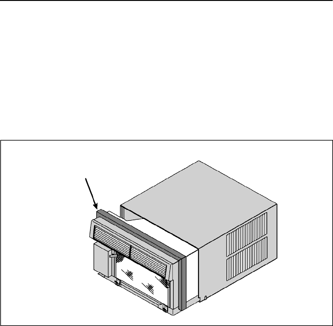
Figure P
Chassis Installation
STEP 1 Slide the chassis into the cabinet stopping approximately 3" from full insertion. Stuff the chassis seal gasket (Item #14) one
inch deep between the chassis and the cabinet (See Figure P). Begin at either bottom corner and go up the side, across the
top, and down the opposite side. Make sure that the gasket is behind the conduit connector (furthest from you). Push the
chassis into the shell the remaining distance so that the plastic front shrouds the front edge of the shell. Fasten the junction
box mounting foot to the shell with the sheet metal screw.
If chassis seal gasket is not installed, the operation of the unit will be negatively affected. Also, the operation noise and
outside noise will be amplifi ed.
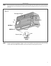
NOTE: Field wiring must be provided to this junction box in accordance with NATIONAL ELECTRIC CODE ARTICLE 501.
Field and equipment grounds are to be terminated at the post in the junction box with the green screw provided. Equipment
power leads are to be connected with the fi eld supply by means of wire nuts (not provided). Install the gasket and cover
plate onto the junction box.
CHASSIS SEAL GASKET


