


15
920-024-05 (12-04)
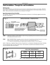
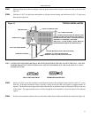
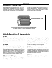
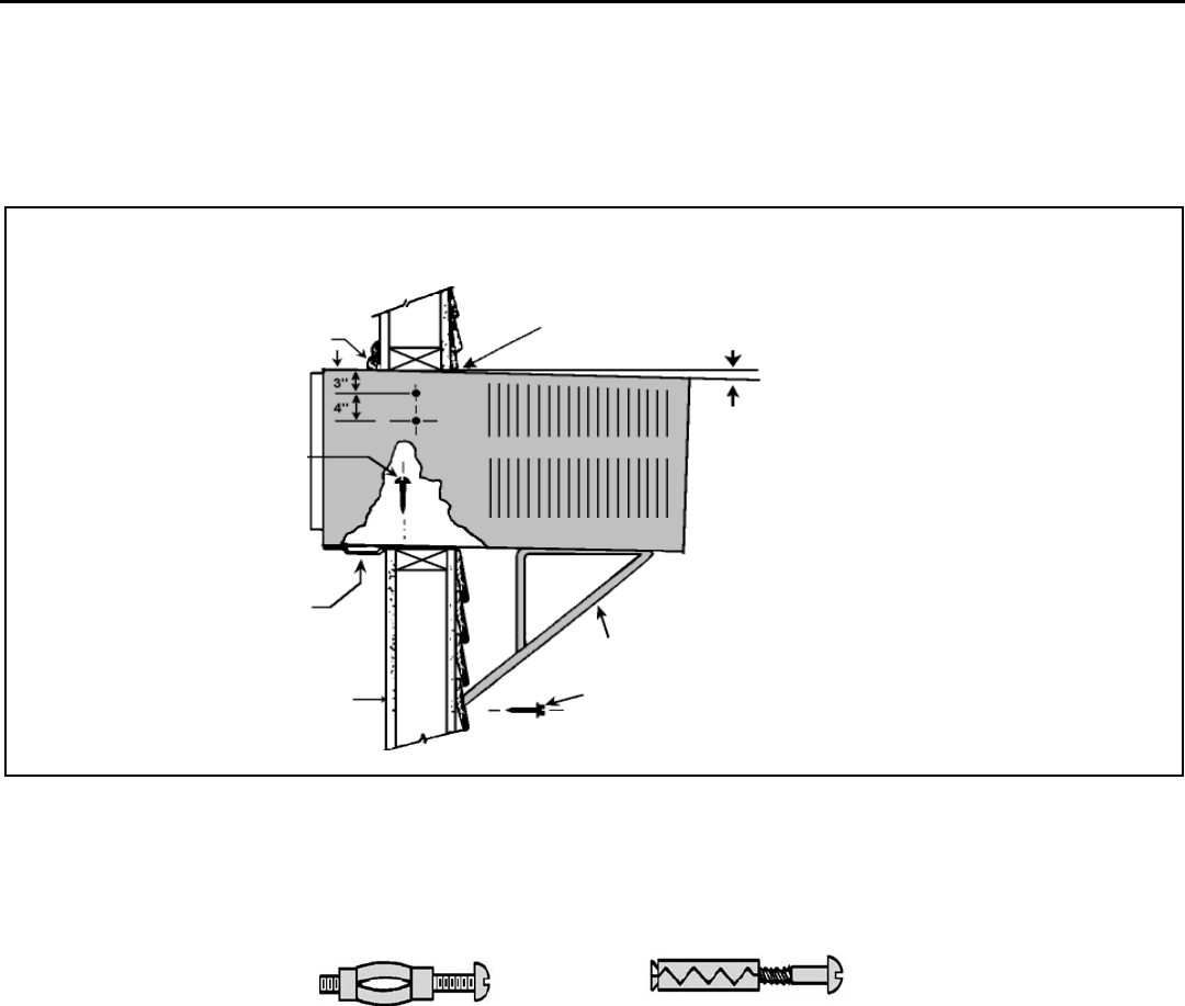
CAULK ALL SIDES AIR TIGHT
TRIM MOULDING
3/8" (10 MM) SLOPE DOWN
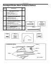
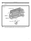
NOTE: SUPPORT BRACKETS MAY BE OMITTED FROM
THROUGH-THE-WALL INSTALLATIONS IF THE CABINET IS
SECURED AS FOLLOWS. DRILL 2 HOLES IN EACH SIDE
AND INSTALL 4 FASTENERS (2 EACH SIDE).
USE #12A X 2" (51 MM) SCREWS, TOGGLE BOLTS OR
EXPANSION ANCHOR BOLTS AS SHOWN IN STEP 5.
SUPPORT BRACKETS (ITEM 1) (SEE NOTE ABOVE)
SCREW #12 X 2" LONG, USE ONE IN EACH
BRACKET. DRILL 5/23 (4 MM) DIA. PILOT HOLES.
SILL PLATE GUIDE CHANNEL
INSIDE WALL SURFACE
SCREW #12A X 2" LONG
USE 3
Figure O
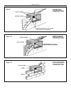
MOLLY OR TOGGLE BOLT EXPANSION ANCHOR BOLT
NOTE: ALTERNATE FASTENERS WHICH MAY BE USED FOR SECURING THE SILL PLATE IN THE WALL, AND THE
SUPPORT BRACKETS TO THE OUTSIDE WALL ARE NOT FURNISHED, BUT ARE AVAILABLE AT A LOCAL
HARDWARE STORE.
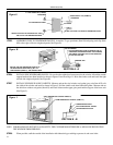
STEP 5 Drill two (2) 5/32" (4 mm) dia. pilot holes in each side at the locations shown (Figure O) and install four (4) #12 x 2" screws
(Item #4). If the hole construction in Step 2 provides a sturdy mount with solid vertical studs, no support brackets are
required. The installation must support the weight of the unit plus an additional weight of 400 pounds (185 kg) on the rear
of the cabinet. The support brackets may be used for through-the-wall installations as shown in Figure O, for additional
support.
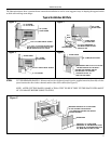
STEP 6 If desired, trim around the cabinet on the room side with a suitable frame molding furnished by the installer (See Figure O).
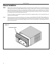
STEP 3 Slide the cabinet into the hole far enough to allow the guide-channel of the sill plate to contact the inside wall surface (See
Figure O).
STEP 4 Drill three (3) 5/32" dia. pilot holes through holes in sill-plate into the framing and install three (3) #12 x 2" long screws
(Item #4) (See Figure O).
TYPICAL INSTALLATION