Page 11
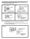
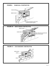
A 1" x 4" or 2" x 4" SPACER SHOULD BE USED BETWEEN THE WALL AND THE SUPPORT BRACKETS WHEN
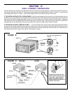
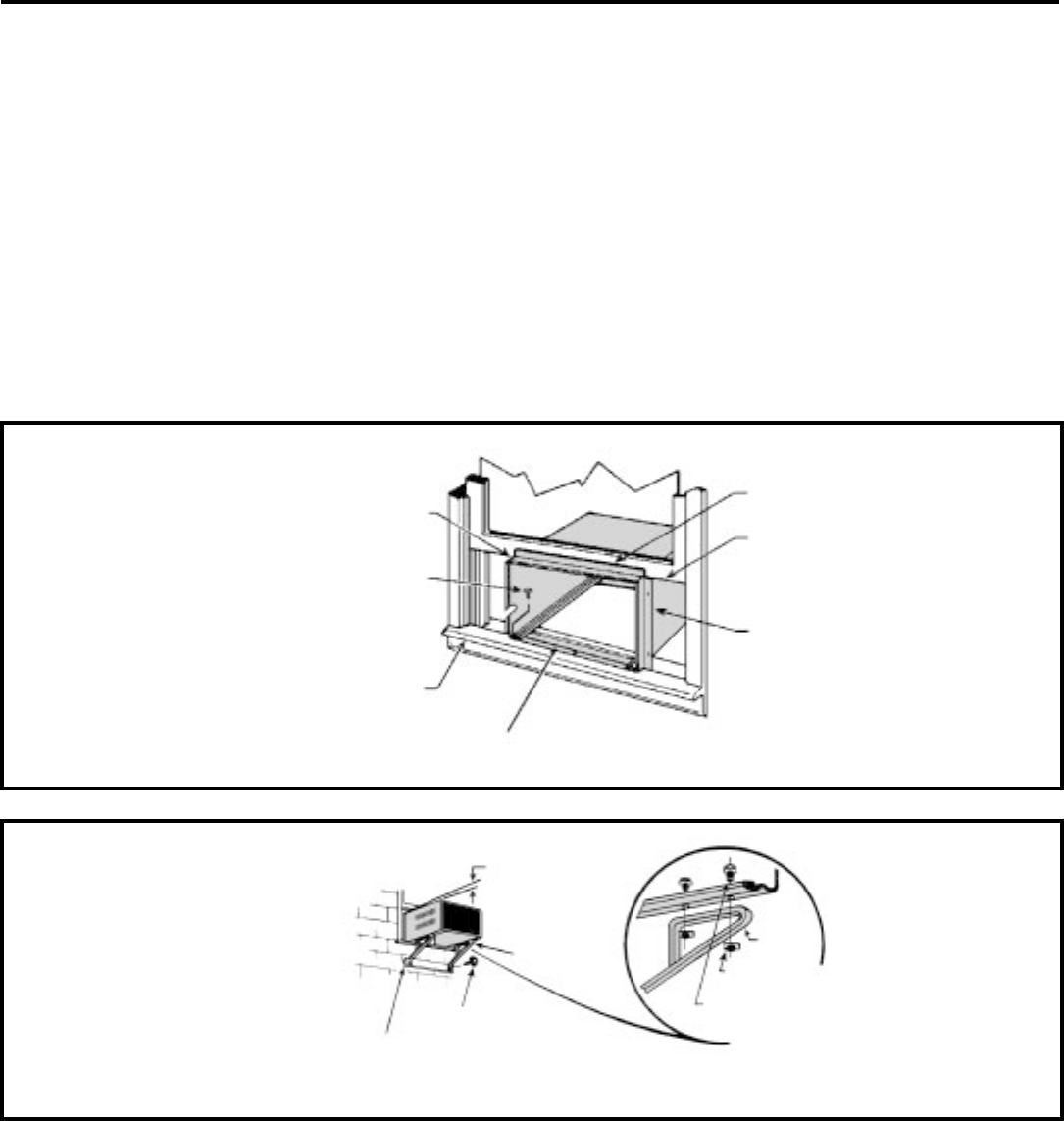
INSTALLED ON ALUMINUM OR VINYL SIDING). Drill 5/32" (4 mm) dia. pilot holes, and secure the brackets to the wall
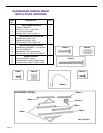
with two (2) #12A x 2" long screws (Item #4). Adjust the support brackets to provide an approximate 3/8" (10 mm) down
slope towards the outside for drainage. Tighten all screws. (See Figure E).
FIGURE D
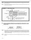
FIGURE E
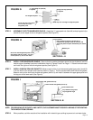
STEP 3. OUTSIDE SUPPORT MOUNTING: Assemble the support brackets (Item #1) to the bottom rails of the cabinet
with four (4) 10-24 1" long screws (Item #2) and four (4) 10–24 flat nuts (Item #3). Adjust the support brackets to
bring the bottom pads in contact with the wall surface. (See Figure E.)
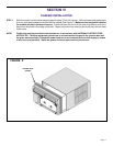
SECTION V — SHELL INSTALLATION
(A) SASH WINDOW INSTALLATIONS
SHELL (CABINET) INSTALLATION – STANDARD SASH WINDOWS
STEP 1. Check the window sill and frame to be sure they are in good condition and firmly anchored to the wall. Repair if
necessary.
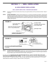
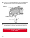
STEP 2. CABINET MOUNTING: Raise the lower window sash 1/4" more than the height of the cabinet. Carefully slide
the cabinet through the open window until the sill plate channel rests behind the window sill and the top support
angle rests against the window (See Figure D). Center the cabinet side to side and drill three (3) 5/32" dia. pilot
holes into the window sill using the holes in the cabinet sill plate as a guide. Install three (3) #12A x 2" long screws
(Item #4) (See Figure D).
Center cabinet side to
side in window
Drill 3 5/32" pilot holes and install 3
#12A x 2" long screws (Item #4)
Window sill
Locate the sill plate guide channel
just back of the window sill.
Top Support Angle
Pull window sash down behind
the top support angle
Side Support Angle
A 1" x 4" or 2" x 4" spacer should be used between the
wall and bracket when installed on aluminum, asbestos
or vinyl siding.
3/8" (10 mm)
Down slope
Support
Bracket
(Item #1)
#12A x 2" Screw (Item #4)
Support
Bracket
10 - 24 Flat Weldnut (Item #3)
10 - 24 x 1" Hex Head Screw (Item #2)


