


22
www.retroaire.com
The Right Fit For Comfort
SEQUENCE OF OPERATION (CONTINUED)
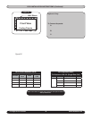
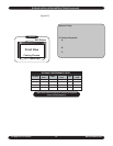
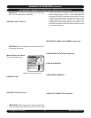
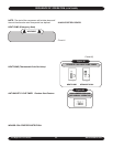
CHOOSING A THERMOSTAT: EMI offers a thermostat
that is compatible with your PTAC/PTHP unit. Select EMI
part number 240-2960 from the latest Retroaire price list
for this option. This is a single stage, cool/heat, mercury
bulb thermostat that can be used in all Retroaire cooling,
heating or heat pump applications. The thermostat has
an adjustable set-point range of between 55°F and 95°F.
There are two independent, adjustable stops that can limit the
heating or cooling range of the thermostat. If a non-mercury,
electronic thermostat is needed, then choose EMI part number
240-3926.
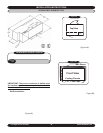
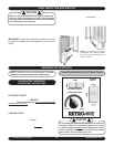
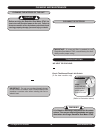
SELECTING A THERMOSTAT “By Others”: When
selecting a thermostat other than those offered by EMI,
it is important to choose a single stage heat/cool, 24V
thermostat. For models 09-17, do NOT select a thermostat
that requires connection to a “C” terminal since these units
do not have provisions for connecting to a “C” terminal.
Only models 19 and 24 have provisions for connecting a
“C” terminal to the unit.
If a thermostat without a “C” terminal is used in a models 19
or 24, then it is important to insulate the unused BROWN “C”
low volt wire to prevent it from shorting at the thermostat.
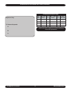
COOLING ONLY WITH ELECTRIC HEAT OR HYDRONIC
HEAT (RC - PTAC’s): Select a thermostat that is compatible
with a cooling - electric heat system. The thermostat should
have “R”, “Y”, “W” and “G” terminals
HEAT PUMP WITH ELECTRIC HEAT (RH - P
THP’S):
Select a thermostat that is compatible with a cooling - single
stage heat - heat pump system. The thermostat should have
“R”, “Y”, “O” and “G” terminals. Retroaire units are single
stage heating only. The electric heat and heat pump will
not operate simultaneously.
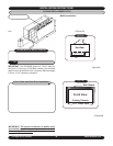
FAN OPERATION: Some thermostats are equipped with
an auto/on fan switch. When this switch is placed in the
on position the indoor fan will run continuous. When the
switch is in the auto position the indoor fan will cycle with
the call for heating or cooling.
FAN PURGE (Optional): After the room thermostat has
been satisfied, the purge feature allows the indoor fan to
remain on for an additional 60 seconds. This increases
efficiency by pulling the remaining energy from the unit.
COOLING OPERATION: After connecting the thermostat
to the unit place the system switch in cool mode. Adjust the
set-point temperature below the room temperature. The
compressor and fan motors will start and cooling will begin.
Place the set-point temperature above the room temperature.
The compressor and condenser fan will stop and the indoor
fan will remain on for an additional sixty seconds.
NOTE: The start of the compressor will not take place until
the anti-short/random start time period has elapsed.
ELECTRIC HEAT OPERATION: Place the thermostat
system switch in heat mode. Adjust the set-point
temperature above the room temperature. The electric
heat will energize along with the indoor fan motor. Heating
will continue so long as the set-point remains above room
temperature. Next place the set-point temperature below
room temperature. The Electric heater will switch off and the
indoor fan will remain on for an additional sixty seconds.
HYDRONIC HEAT OPERATION (Optional): An optional
hydronic heat package may be selected in lieu of electric
heat. Heating operation is essentially the same as that of
units with electric heat. With the thermostat system switch
set to heat and the set-point temperature above room
temperature, the hydronic valve will open allowing water
to flow through the coil. The indoor fan will also switch on
and warm air will flow from the unit. Heating will continue
so long as the set-point remains above room temperature.
Place the set-point temperature below room temperature.
The hydronic valve will close and indoor fan will switch off
after the sixty-second purge time has elapsed. The hydronic
valve is a 24Vac normally open valve. Should power be lost
to the unit, the valve will default to the open position.
HEAT PUMP (Cooling Mode
): Cooling operation in a heat
pump unit is described in “Cooling operation” above. The
unit is equipped with a reversing valve that is energized for
cooling and de-energized in heating mode.
HEAT PUMP (Heating Mode
): Heat pump units are “Limited
Range” equipped with back-up electric resistance heat.
Limited Range heat pumps are designed to operate when
outdoor temperatures are between 75°F and 40°F and with
a maximum indoor temperature of 80°F. When the outdoor
temperature falls below approximately 40°F the unit will
switch from heat pump to electric resistance heat. Electric
heat will then remain as the heat source until the outdoor
temperatures rise above 50°F. Retroaire heat pumps (RH
– PTHP) are single-stage heating units. The electric heat
and heat pump will NOT operate simultaneously.
To operate the unit in heating mode, it must first be connected
to an appropriate heat pump thermostat. (See choosing a
thermostat). Select heat on the thermostat system switch.
Then, adjust the set-point temperature above the room
temperature. The compressor and fan motors will start
and heating will begin. If the outdoor temperature is below
approximately 40°F the heat pump system will not operate.
Electric heat will then take over the heating demand.
Heating will continue so long as the set-point temperature
remains above the room temperature. Place the set-point
REMOTE THERMOSTAT OPERATIONAL INSTRUCTIONS