


19
www.retroaire.com
The Right Fit For Comfort
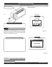
RC/RH90 FINAL INSPECTION
AND START-UP
( All other units see “Final Inspecton and Startup” page 20)
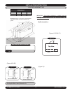
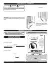
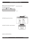
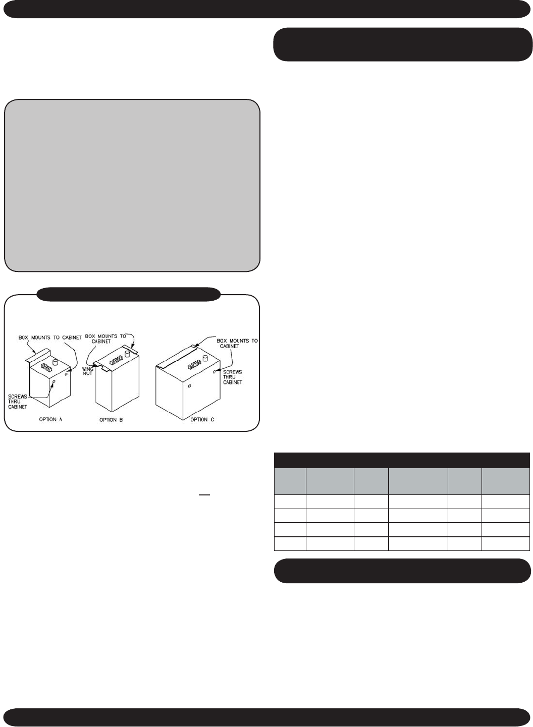
1. Mount control box in wall sleeve (in the same location
as the old control box)
2. Make sure the chassis is level. Check by pouring water
into the drain pan and making certain it flows through
the drain hoses to the condenser side of the unit.
3. Hard wire line voltage to control box and plug cooling
chassis line cord into control box receptacle and Molex
plugs.
IMPORTANT
: Follow the information provided on the
rating plate for voltage and amperage/fuse size for proper
supply.
4.
Attach the front panel to the existing cabinet enclo-
sure.
5. Turn the power on.
6. Check for proper operation (i.e., cooling, optional fresh
air, and heating if supplied).
7. Check to be sure nothing will interfere with the room
discharge air or the return air to the units (i.e., curtains
or drapes that obstruct the air flow or plush carpeting
that can obstruct the return air. Items like these can
cause serious damage to the chassis and can void the
warranty.
8. See Sequence of Operation pages 20- 22.
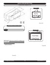
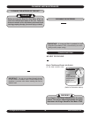
RC/RH90 INSTALLATION INSTRUCTIONS (Continued)
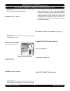
Hydronic Only: Remove the 2-position connector as-
sembly from kit bag supplied with unit (this will have 2
yellow wires attached). Connect this 2-position connec
-
tor to the 2-position connection located on the bottom
of the control box panel.
To Connect Aquastat:
A. Remove the black jumper wire located on the
bottom panel of the control box (this is also ter-
minated with a 2-position connector).
B. Cut the jumper wire in the middle and splice the
aquastat to the jumper.
C. Place the connecter back into original location.
Refer to wire diagram on the unit for details.
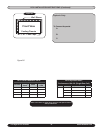
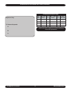
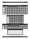
*Refer to the charts on page 23 for electrical and optional
electric heat specifications.
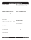
RC/RH 90 Performance Date*
UNIT
SIZE
COOLING
BTUH
EER
HEAT PUMP
BTUH
COP
FRESH
AIR CFM
9 9,500 10 8500 2.8 40/35
12 11,900 10 11400 2.9 40/35
15 14,700 9.2 13800 2.8 40/35
18 16,900 9.1 N/A N/A 40/35
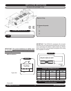
7. Install the control section:
• In a standard unit mount installation, take the thermal
bulb from the control section and run the line along the
unit to the blower section. There will be no thermostat
bulb if a remote thermostat option is used.
• While looking at the sides of the blower housing,
there are two clips that will support the thermal bulb.
Take out the screws that hold these clips and slide
the thermal bulb into the clips.
• Fasten the clips back into place, making sure you do not
kink the bulb as you might break the thermostat end.
• After the thermostat is back in place, reinstall the front
cover of the unit and finish the installation.
8. Connect line cord.
9. See Final Inspection and Startup page 20.
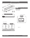
6. Once confident that all seals are the correct size and in
the proper location and the correct baffles are attached
to the condenser coil and in the proper orientation, slide
unit into final position and tighten any tie down bolts or
screws as necessary.
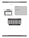
Select one of the following which properly matches the
control box of your unit.
RC 90 CONTROL BOX OPTIONS