24
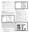
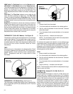
THERMOSTAT - Models ES, YS, EM, YM, EL, YL
(See Figure 32)
A cross ambient thermostat is used on all heat pump and
electric heat units. In addition to cycling the unit in a heating
or cooling operation, the thermostat will terminate the cooling
cycle in the event ice forms on the evaporator coil, in this
case the thermostat functions as a de-ice control. A resistor
(anticipator) is positioned within a plastic block to supply a
small amount of heat to the bulb area to prevent long "off
cycles" in the "Cool-Fan Auto" (MoneySaver) position (see
Figure 8.) A current feedback through the fan motor windings
during "off cycle" completes the circuit to the resistor.
TEST:
1. Remove leads from thermostat.
2. Turn thermostat knob clockwise to its coldest position.
3. Test for continuity between the two terminals. Contacts
should be closed.
4. Turn thermostat knob counterclockwise to its warmest
position.
5. Test for continuity - contacts should be open.
NOTE: The thermostat must be within the temperature
range listed to open and close.
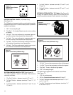
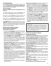
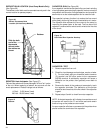
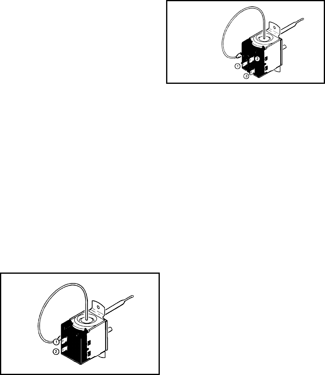
THERMOSTAT ("YQ" Model Only) (See Figure 31)
This thermostat is single pole-double throw, cross ambient
with a range of 60° to 92°F and a differential of ±2°F. Terminal
"2" is common.
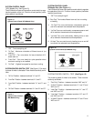
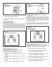
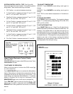
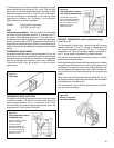
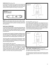
THERMOSTAT ("SQ & KQ" Models) - See Figure 30.
Thermostat is used to cycle the compressor on and off at the
comfort level desired. The thermostat has a range from 60°
±2°F to 90° ±4°F, with a differential of 5°F. Turning the knob
clockwise lowers the indoor room temperature setting, while
turning the knob counter clockwise raises the indoor
temperature.
TEST:
Remove wires, turn thermostat to its coldest position. Check
for continuity between the two terminals. Turn thermostat to
warmest position, check continuity to see if contacts open.
NOTE: Temperature must be in range listed to check
thermostat.
To maintain the comfort level desired, a cross ambient type
thermostat is used. The thermostat has a range from 65° ±2°F
to 87° ±3°F. The thermostat bulb is positioned in front of the
evaporator coil to sense the return air temperature. Thermo-
stat malfunction or erratic operation is covered in the trouble-
shooting section of this manual.
TEST:
1. Remove leads from thermostat.
2. Turn thermostat knob clockwise to its coldest position.
3. Test for continuity between the two terminals. Contacts
should be closed.
4. Turn thermostat knob counterclockwise to its warmest
position.
5. Test for continuity - contacts should be open.
NOTE: The thermostat must be within the temperature range
listed to open and close.
Figure 30
Thermostat
(QME Units) The Fan Speed button and the Warmer button.
( XQ Units) The Fan Speed button and the Temp Up button.
The indoor temperature will be displayed for 10 seconds. The
display will change back to the Set Point temperature by
pressing any key button except for the On/Off button. The
indoor temperature can be viewed in all modes, including test
mode.
Filter Alert: The Filter Alert indicator turns on after the fan
motor has been operating for 250 hours. The Filter Alert
indicator is reset by pressing the Filter Alert button one time
only,. Power failures will not reset the 250 hour timer. All time
elapsed is stored in memory and resumes counting after power
is restored.
Keep Alive: The electronic control has a memory to retain all
functions and status as set up by the user in the event of a
power failure. Once power is restored to the unit there is a
two second delay before the fan comes on and approximately
three minutes delay before the compressor is activated,
providing that the mode was set for cooling and the set point
temperature has not been met in the room.
Figure 31
Thermostat
(YQ Models Only)


