


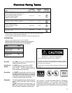
17
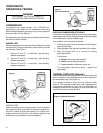
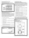
SYSTEM CONTROL PANEL
("KQ" Models Only- See Figure 10)
The KQ Model unit uses a five position control switch to regu-
late the operation of the unit. Function of each position (clock-
wise rotation) is as follows:
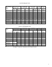
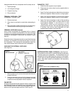
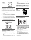
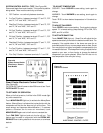
SYSTEM CONTROL SWITCH - TEST (See Figure 11) Turn knob
to phase of switch to be tested. There must be continuity as fol-
lows:
1. "Hi Fan" Position - between terminals "L1" and "H".
2. "Low Fan" Position - between terminals "L1" and "L".
3. "Low Cool" Position - between terminals "L1" and "L" and
"C".
4. "Hi Cool" Position - between terminals "L1" and "H" and "C".
Figure 11
System Control Switch
(KQ Models Only)
1. "Off" - Turns everything off.
2. "Hi Fan" - Maximum circulation of filtered room air (no
cooling.)
3. "Low Fan" - Fan runs slower for less circulation of fil-
tered room air.
4. "Low Cool" - Fan runs slowly for quiet operation when
maximum cooling is not needed.
5. "Hi Cool" - Highest fan speed for maximum cooling.
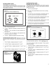
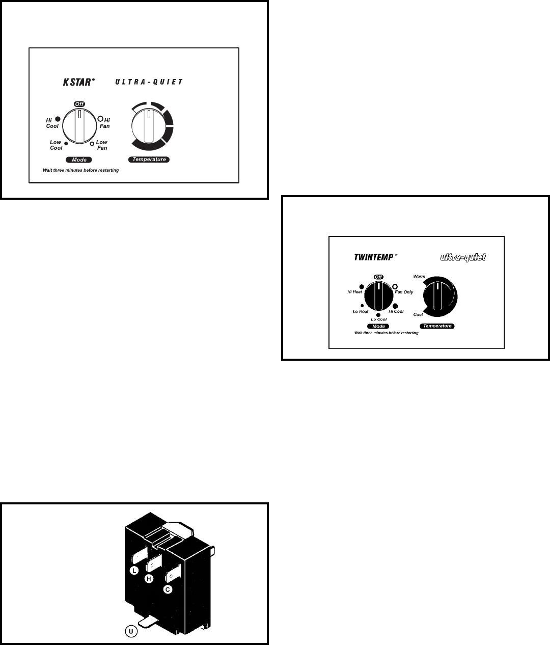
Figure 10
System Control Panel (KQ Models Only)
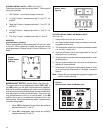
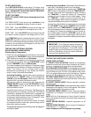
SYSTEM CONTROL PANEL
EQ Model Only (See Figure 12 )
The EQ Model unit uses a six-position control switch to regulate
the operation of the unit. Function of each position (clockwise
rotation) is as follows:
1. “Off” Turns everything off.
2. “Fan Only” To circulate filtered room air, but no cooling
or heating
3. “Hi Cool” Fan runs continuously, compressor goes on
and off to maintain the selected room temperature
4. “Lo Cool” fan runs continuously, compressor goes on and
off to maintain the selected room temperature.
5. “Lo Heat” Fan runs continuously, heating turns on and
off to maintain the selected room temperature.
6. Hi Heat” Fan runs continuously, heating turns on and off
to maintain the selected room temperature.
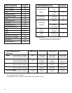
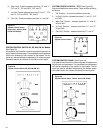
SYSTEM CONTROL SWITCH – TEST (See Figure 13)
Turn knob to phase of switch to be tested. There must be
continuity as follows:
1. “Fan Only” Position – between terminals “MS” and “H”
2. “Hi Cool” Position – between terminals “L1” and “C” and
“MS” and “H”
3. “Low Cool” Position – between terminals “L1” and “C”
and “MS” and “LO”
4. “Low Heat” Position – between terminals “L2” and “2”
and “MS” and “LO”
5. “Hi Heat” Position – between terminals “L2” and “2” and
“MS” and “H”
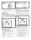
Figure 12
System Control Panel (EQ Models only)