


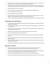
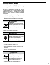
FAN MOTOR
SWITCH, ON-OFF
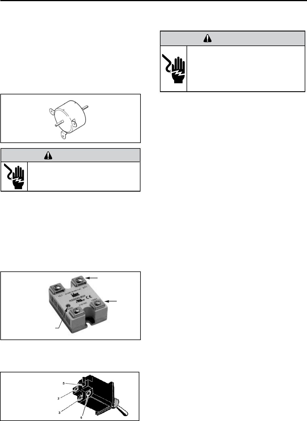
Line side
SOLID STATE
RELAY
Load
side
LED indicates
contacts closed
when lit
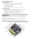
FAN MOTOR
A 230 volt single phase permanent split capacitor motor
is used to drive the evaporator blower and condenser
fan. A running capacitor is wired across the start and run
terminals of the motor.
The motor is totally enclosed and is protected with a
line voltage overload located internally of the motor. The
motor shaft is stainless steel to resist corrosion. When
the unit is turned on, the motor runs continuously.
FAN MOTOR – TEST
1. Determine that the capacitor is good.
2. Perform continuity test on windings to determine if
open, shorted or okay.
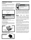
SOLID STATE RELAY
Two 50 amp rated 208/230 volt solid state relays are used
to energize the compressor and fan motor. Terminals 3
and 4 are the 208/230 volt line side. Terminals 1 and 2
are load side contacts.
SYSTEM CONTROL SWITCH
This switch is double pole, single throw. Check for
continuity between terminals 2 and 3, and 5 and 6.
COMPONENT TESTING
CAPACITORS
Many motor capacitors are internally fused. Shorting the
terminals will blow the fuse, ruining the capacitor. A 20,000
ohm 2 watt resistor can be used to discharge capacitors
safely. Remove wires from capacitor and place resistor
across terminals. When checking a dual capacitor with
a capacitor analyzer or ohmmeter, both sides must be
tested.
Capacitor Check with Capacitor
Analyzer
The capacitor analyzer will show whether the capacitor
is “open” or “shorted.” It will tell whether the capacitor
is within its micro farads rating and it will show whether
the capacitor is operating at the proper power-factor
percentage. The instrument will automatically discharge
the capacitor when the test switch is released.
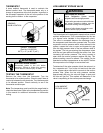
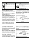
Capacitor Connections
The starting winding of a motor can be damaged by a
shorted and grounded running capacitor. This damage
usually can be avoided by proper connection of the
running capacitor terminals.
From the supply line on a typical 230 volt circuit, a 115 volt
potential exists from the “R” terminal to ground through a
possible short in the capacitor. However, from the “S” or
start terminal, a much higher potential, possibly as high as
400 volts, exists because of the counter EMF generated
in the start winding. Therefore, the possibility of capacitor
failure is much greater when the identifi ed terminal is
connected to the “S” or start terminal. The identifi ed
terminal should always be connected to the supply line, or
“R” terminal, never to the “S” terminal.
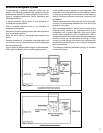
When connected properly, a shorted or grounded running
capacitor will result in a direct short to ground from the “R”
terminal and will blow the line fuse. The motor protector will
protect the main winding from excessive temperature.
ELECTRIC SHOCK HAZARD
WARNING
Turn off electric power before servicing.
Discharge capacitor with a 20,000 Ohm 2 Watt
resistor before handling.
Failure to do so may result in personal injury,
or death.
ELECTRIC SHOCK HAZARD
WARNING
Disconnect power to the unit before
servicing. Failure to follow this warning
could result in serious injury or death.
11