


22
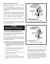
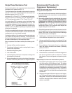
Single Phase Resistance Test
Remove the leads from the compressor terminals and set the
ohmmeter on the lowest scale (R x 1).
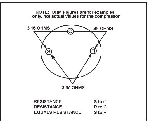
Touch the leads of the ohmmeter from terminals common to
start ("C" to "S"). Next, touch the leads of the ohmmeter from
terminals common to run ("C" to "R").
Add values "C" to "S" and "C" to "R" together and check resis-
tance from start to run terminals ("S" to "R"). Resistance "S"
to "R" should equal the total of "C" to "S" and "C" to "R."
In a single phase PSC compressor motor, the highest value
will be from the start to the run connections (“S” to "R"). The
next highest resistance is from the start to the common con-
nections ("S" to "C"). The lowest resistance is from the run to
common. ("C" to "R") Before replacing a compressor, check
to be sure it is defective.
Check the complete electrical system to the compressor and
compressor internal electrical system, check to be certain that
compressor is not out on internal overload.
Complete evaluation of the system must be made whenever
you suspect the compressor is defective. If the compressor
has been operating for sometime, a careful examination must
be made to determine why the compressor failed.
Many compressor failures are caused by the following condi-
tions.
1. Improper air fl ow over the evaporator.
2. Overcharged refrigerant system causing liquid to be re-
turned to the compressor.
3. Restricted refrigerant system.
4. Lack of lubrication.
5. Liquid refrigerant returning to compressor causing oil to
be washed out of bearings.
6. Noncondensables such as air and moisture in the system.
Moisture is extremely de structive to a refrigerant system.
Recommended Procedure for
Compressor Replacement
NOTE: Be sure power source is off, then disconnect all
wiring from the compressor.
1. Be certain to perform all necessary electrical and refrigera-
tion tests to be sure the compressor is actually defective
before replacing .
2. Recover all refrigerant from the system though the process
tubes. PROPER HANDLING OF RECOVERED RE-
FRIGERANT ACCORDING TO EPA REGULATIONS IS
REQUIRED. Do not use gauge manifold for this purpose
if there has been a burnout. You will contaminate your
manifold and hoses. Use a Schrader valve adapter and
copper tubing for burnout failures.
3. After all refrigerant has been recovered, disconnect suction
and discharge lines from the compressor and remove com-
pressor. Be certain to have both suction and discharge
process tubes open to atmosphere.
4. Carefully pour a small amount of oil from the suction stub
of the defective compressor into a clean container.
5. Using an acid test kit (one shot or conven tional kit), test
the oil for acid content according to the instructions with
the kit.
6. If any evidence of a burnout is found, no matter how
slight, the system will need to be cleaned up following
proper procedures.
7. Install the replacement compressor.
8. Pressurize with a combination of R-22 and nitrogen and
leak test all connections with an electronic or Halide
leak detector. Recover refrigerant and repair any leaks
found.
Repeat Step 8 to insure no more leaks are present.
9. Evacuate the system with a good vacuum pump capable
of a fi nal vacuum of 300 microns or less. The system
should be evacuated through both liquid line and suction
line gauge ports. While the unit is being evacuated, seal
all openings on the defective compressor. Compressor
manufacturers will void warranties on units received not
properly sealed. Do not distort the manufacturers tube
connections.
10. Recharge the system with the correct amount of refriger-
ant. The proper refrigerant charge will be found on the unit
rating plate. The use of an accurate measuring device,
such as a charging cylinder, electronic scales or similar
device is necessary.