


2
Table of Contents
Introduction ......................................................................3
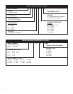
Vert-I-Pak Model Number Identifi cation Guide ..............4
Serial Number Identifi cation Guide .................................4
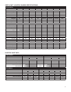
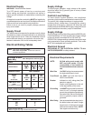
H Suffi x Chassis Specifi cations ......................................5
E and G Suffi x Chassis Specifi cations ............................6
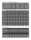
A and D Suffi x Chassis Specifi cations ............................7
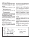
Sequence Of Operation ...................................................8
Electrical Supply ..............................................................9
Supply Circuit ...................................................................9
Supply Voltage .................................................................9
Control (Low) Voltage ......................................................9
Supply Voltage .................................................................9
Electrical Ground .............................................................9
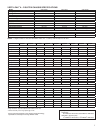
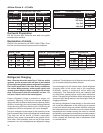
Electrical Rating Tables ...................................................9
Electrical Requirements ...................................................9
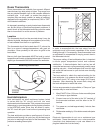
Room Thermostats ........................................................10
Thermostat Location ......................................................10
Heat Anticipators ..........................................................10
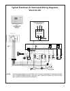
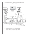
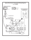
Electrical & Thermostat Wiring Diagrams ................11-13
Indoor Blower - Air Flow ................................................14
Condenser Fan Motors ..................................................14
Blower Wheel Inspection ...............................................14
Cooling ...........................................................................14
Heating (Electric) ..........................................................14
External Static Pressure ................................................14
Checking External Static Pressure ...............................15
Checking Approximate Airfl ow ......................................15
Electric Heat Strips ........................................................15
Airfl ow Charts ................................................................16
Refrigerant Charging .....................................................16
Method Of Charging ......................................................17
Undercharged Refrigerant Systems ..............................17
Overcharged Refrigerant Systems ................................18
Restricted Refrigerant Systems .....................................18
Capillary Tube Systems .................................................19
Reversing Valve — Description/Operation ...................19
Electrical Circuit And Coil ..............................................19
Testing Coil ....................................................................19
Checking Reversing Valves ...........................................20
Touch Testing Heating/Cooling Cycle ..........................20
Procedure For Changing Reversing Valve ....................20
Compressor Checks ......................................................21
Locked Rotor Voltage Test ............................................21
Single Phase Connections ...........................................21
Determine Locked Rotor Voltage .................................21
Locked Rotor Amperage Test ........................................21
Single Phase Running & Locked Rotor Amperage .......21
External Overload ..........................................................21
Checking the External Overload ...................................21
Checking the Internal Overload .....................................21
Compressor Single Phase Resistance Test .................22
Compressor Replacement .............................................22
Capacitors ......................................................................23
Capacitor Check With Capacitor Analyzer ....................23
Capacitor Connections ..................................................23
Emergency Heat Switch ................................................24
Wiring Diagram Index ..............................................25-26
9-18 Electrical Troubleshooting Chart – Cooling .........39
2-Ton Electrical Troubleshooting Chart – Cooling .......40
Refrigerant System Diagnosis – Cooling ......................41
Refrigerant System Diagnosis – Heating ......................41
Electrical Troubleshooting Chart –Heat Pump .............42