


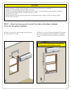
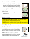
If you have excess connecting line, roll the line into a coil approximately 2 feet wide,
secure with the provided wire ties and store between the outdoor module and the
wall. DO NOT cut or kink the connecting line!
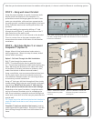
STEP 8 – Connect the electrical connector from the connecting
line to outdoor module
1. Connect the black colored electrical connector from the connecting line into the
mating connector on the outdoor module. The connectors will snap into place with a
click. (The plug can be removed by pushing in the side tabs on the plug and pulling
the plug body down and out of the receptacle.)
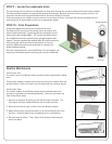
2. Install the electrical cord retention bracket (Item #6 in the Accessories List) using
two #8 x 3/4” screws (Item #10 in the Accessories List). The opening in the electrical
cord retention bracket should t over the cord. Do not pinch the cord in the bracket.
3. Install the plastic cover (Item #2 in the Accessories List) as shown. There is one
screw located on the lower right ange of the cover and one screw under the elec-
trical connector access cover. Once secure, use enclosed screw (Item #10 in the
Accessories List) to close the access door.
4. Install the quick connect cover as shown in gure 4. Once in place secure using
enclosed #8 x 3/4” screw located on the top ange of the quick connect cover.
All Covers must be in place to operate unit.
SHOCK HAZARD exists without electrical access cover.
Cover cannot be installed without completing steps 8.1 through 8.4 properly.
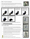
6. Install security screw
(Item 13 in the Accessories
List) to prevent tampering
with line-set connector
mechanism.
3.
2.
1.
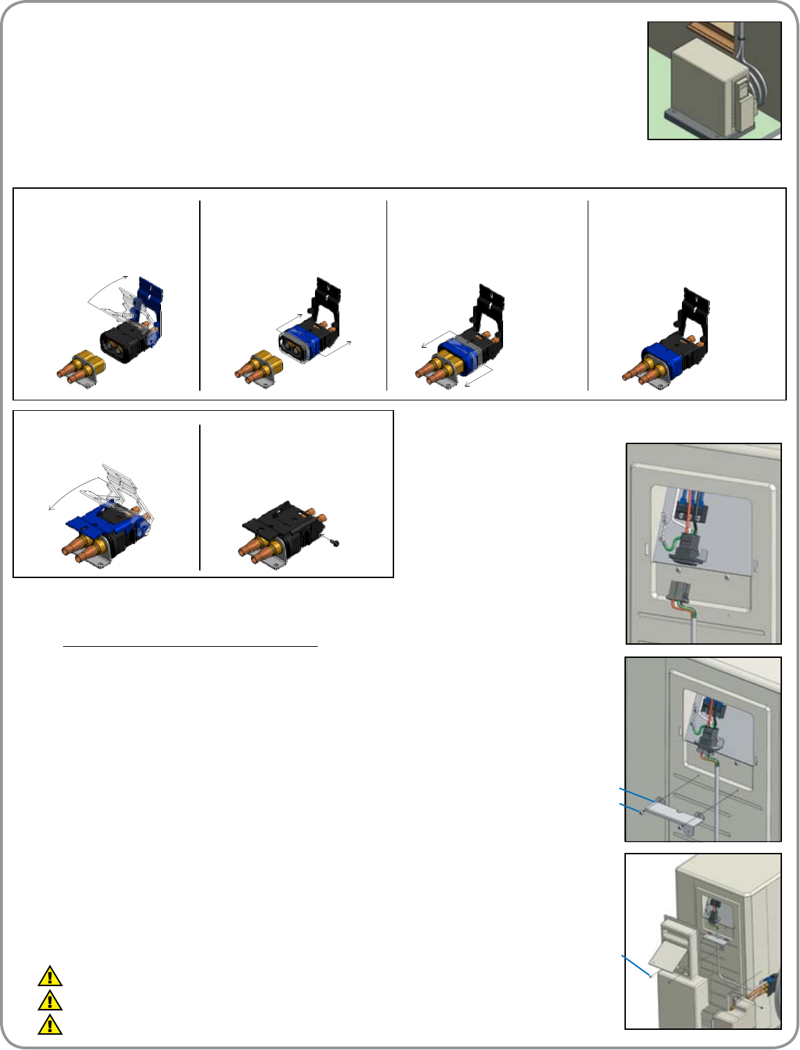
1. Open lock handle on line-
set connector by pulling
back and rotating toward
indoor unit.
2. Grasp outer lock collar on
line-set connector and pull
back until it stops.
3. While holding outer lock
collar rearward, push line-
set connector body over
base connector on outdoor
unit half way and release
outer lock collar.
4. Continue to push line-set
connector onto base con-
nector until outer lock col-
lar engages base connector.
The outer lock collar will
snap into position with base
connector and a click will
be heard.
5. Grasp lock handle and
rotate to its closed posi-
tion.
Item #6
Item #10
Item #10
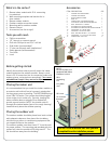
STEP 7 – Connect the quick connector from the indoor line set outdoor module.
STEP 6 - Place the mounting pad.
Position the mounting pad so that the mounting holes are away from the house. Set the
outdoor module on the mounting pad so that the module feet align with the mounting holes.
Screw the outdoor module to the mounting pad with the 4 condenser pad installation washers
and screws provided (Items #8 and #9 in the Accessories List).
STEP 6