


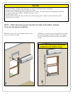
STEP 4 - Line set installation
The Breeze connecting line set contains copper tubing that may kink if bent or formed incorrectly or repeatedly.
To avoid damaging your Breeze air conditioning system follow the 3 rules below throughout installation:
1) DO NOT uncoil and recoil the connecting line set more than two times.
2) DO NOT bend tubing in a radius smaller than 6”
3) ALWAYS use the tube bending guide when making bends greater than 45°
Following these instructions is critical for proper installation and to avoid damage to the unit. Damage to the
connecting line due to improper installation will not be covered by the warranty.
4.1 Option 1 (3” hole pass through)
Completely uncoil the line set as straight as possible. Starting with the quick connect end of the line set, pass the entire
length through the 3” hole. (Before installation break small plastic knockout on side of indoor unit for power cord to
pass through-see Step 3, Figure 3.1).
4.2 Option 2 (SimpleSill
™
window installation)
Uncoil enough of the line set to completely pass through the SimpleSill. Pre bend
the line set using the enclosed template to match the desired shape as it passes
through the SimpleSill. Place remaining coiled line set outside the window for
later connection to the outdoor unit. Break full plastic knockout for line set to pass
through the side of the indoor unit-see Step 3, Figure 3.2.
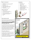
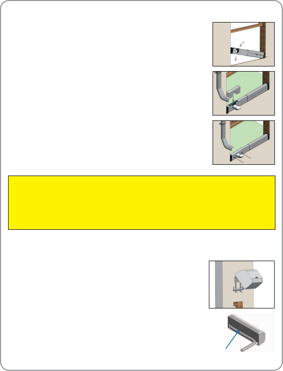
STEP 5 - Hang the indoor module on the wall bracket.
Hang the module at the top rst and rotate it down until the module is level with the
wall. (You may need to make adjustments to the connecting line to get the indoor
module to mount cleanly) The Breeze module is not designed to mount totally ush
to the wall. A space of 1/8” to 3/8” may be present between the module and the
wall.
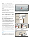
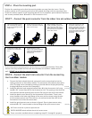
1. Be sure window sill is clean and free of dirt and debris. With the window raised,
place bottom seal gasket (trimmed to window width) rmly against window sill
(adhesive side down). Expand the SimpleSill™ 1” greater than the width of the win-
dow and install the securing pin. Place one end of the SimpleSill™ into the window
opening so it is against the corner of the window frame and sill. Raise the other
side of the SimpleSill™ 6-9 inches (depending on window width) above the window
sill. Next, press the raised side down until the SimpleSill™ is lodged securely into
position. The SimpleSill™ end gaskets will conform to the window track shape.
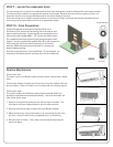
2. Reference Step 4.2 and pass the connecting line out the window and insert it into
the connecting line form in the SimpleSill™.
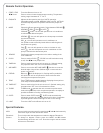
3. Install top seal gasket to the bottom of the window so it will seal against the top of
the SimpleSill.
4. Replace the pass through cover.
5. Insert securing pins.
6. Lower window frame against SimpleSill compressing gasket.
7. Depending on the type of window, install the appropriate security lock as recom-
mended by manufacturer.
Option 2: Window Installation Using Friedrich SimpleSill™
1.
4.
5.
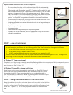
STEP 5
The line set will sit in the recess of the
back of the indoor unit when mounted.