


14
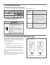
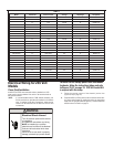
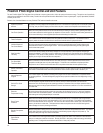
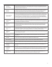
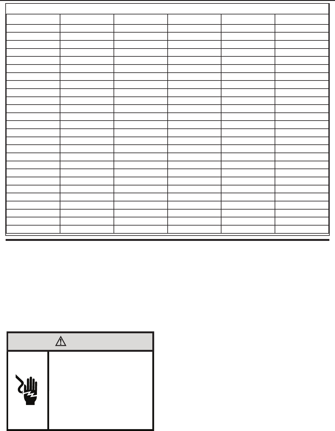
TABLE 2
Model Heater kW Power Cord Kit Voltage Amperage Receptacle
PDE07K 0.0 PXPC23000 230/208 15 NEMA 6-15r
PDE/PDH07K 2.0 PXPC23015 230/208 15 NEMA 6-15r
3.0 STD 230/208 20 NEMA 6-20r
PDE09K 0.0 PXPC23000 230/208 15 NEMA 6-15r
PDE/PDH09K 2.0 PXPC23015 230/208 15 NEMA 6-15r
3.0 STD 230/208 20 NEMA 6-20r
5.0 PXPC23030 230/208 30 NEMA 6-30r
PDE12K 0.0 PXPC23000 230/208 15 NEMA 6-15r
PDE/PDH12K 2.0 PXPC23015 230/208 15 NEMA 6-15r
3.0 STD 230/208 20 NEMA 6-20r
5.0 PXPC23030 230/208 30 NEMA 6-30r
PDE15K 0.0 PXPC23000 230/208 15 NEMA 6-15r
PDE/PDH15K 2.0 PXPC23015 230/208 15 NEMA 6-15r
3.0 PXPC23020 230/208 20 NEMA 6-20r
5.0 STD 230/208 30 NEMA 6-30r
PDE/PDH07R 2.0 PXPC26515 265 15 NEMA 6-15r
3.0 STD 265 20 NEMA 6-20r
PDE/PDH09R 2.0 PXPC26515 265 15 NEMA 6-15r
3.0 STD 265 20 NEMA 6-20r
5.0 PXPC26530 265 30 NEMA 6-30r
PDE/PDH12R 2.0 PXPC26515 265 15 NEMA 6-15r
3.0 STD 265 20 NEMA 6-20r
5.0 PXPC26530 265 30 NEMA 6-30r
PDE/PDH15R 2.0 PXPC26515 265 15 NEMA 6-15r
3.0 PXPC26520 265 20 NEMA 6-20r
5.0 STD 265 30 NEMA 6-30r
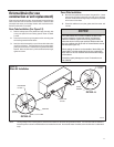
Electrical Wiring for 265 Volt
Models
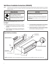
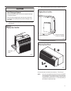
NOTE: It is recommended that the PXSB subbase assembly, the
PXCJA conduit kit (or equivalent) be installed on all hardwire
units. If installing a ush-oor mounted unit, make sure the
chassis can be removed from the sleeve for service and
maintenance.
WARNING
Electrical Shock Hazard
Turn off electrical power before service
or installation.
ALL electrical connections and wiring
MUST be installed by a qualified
electrician and conform to the National
Code and all local codes which have
jurisdiction.
Failure to do so can result in property
damage, personal injury and/or death.
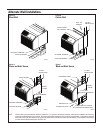
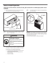
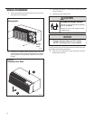
Power Cord Installation
All 265V PTAC/PTHP units come with a factory installed non-LCDI
power cord for use in a subbase. If the unit is to be hard-wired refer to
the instructions below.
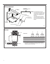
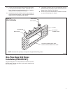
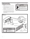
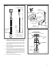
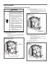
To install the line voltage power leads and conduit
to chassis, follow the instructions below and refer
to Figures 25-27 on page 19. PXCJA Conduit Kit
is required with this setup.
1. Follow the removal process of the chassis’s junction box
(Figure 25, step 2, page 19).
2. Prepare the 265V (or 230V) power cord for connection to the chas-
sis’ power cord connector by cutting the cord to the appropriate
length (refer to Figure 26 and follow Figure 15). Power cord harness
selection shown on Table 2 on page 14.