


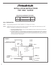
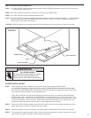
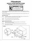
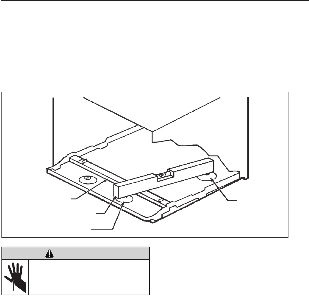
FIGURE 2
BACK UNIT REST
LEVEL
FRONT UNIT REST
RAISED LEDGE
INSTALLATION REQUIREMENTS:
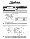
STEP 1 The “WSC” SLEEVE should be positioned so that the DRAIN EXTENSION extends a minimum of 9/16” beyond the
OUTSIDE WALL (See Figure 1).
STEP 2 The “WSC” SLEEVE must extend a minimum of 7/8” beyond the INSIDE WALL.
STEP 3 The “WSC” SLEEVE must be installed level side to side.
STEP 4 The “WSC” SLEEVE must also be installed with a downward tilt toward the outside of the building. If a level is placed
so that it rests on the FRONT and BACK UNIT REST as shown in Figure 2, a properly installed unit provides a 1/2
bubble slope to the outside of the building.
CAUTION: SLEEVE projections and leveling precautions must be observed to prevent the entry of water into the room.
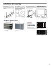
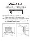
SLEEVE INSTALLATION:
STEP 1
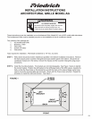
After unpacking the “WSC” SLEEVE from the carton, remove the corrugated FRONT PANEL.
For immediate installation of sleeve and chassis (skip if installing chassis into sleeve at a later date):
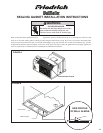
Remove the rear WEATHER PANEL. Reverse grille and place lower edge into sleeve tab (Friedrich logo facing
out). Align slots with screw holes. Secure grille with screws.
Place “WSC” SLEEVE in the wall opening following the instructions given in the INSTALLATION REQUIRE-
MENTS section. Attach the SLEEVE to the INSIDE WALL by driving two #12A x 2” screws in each side of the
SLEEVE (see Figure 1.). Shim at the top of the SLEEVE, midway between the sides. Drive one #12A x 2” screw
in the top of the sleeve, close to the shim. Install screws from inside the SLEEVE. If the wall opening is not
framed with wood, use expansion anchor bolts or molly (toggle) bolts (not provided).
MECHANICAL HAZARD
WARNING
Sharp edges and corners. Be careful with
the sharp edges and corner. Wear protective
clothing and gloves, etc.
Failure to do so could result in serious injury.
STEP 2
STEP 3
STEP 4
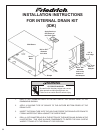
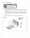
Once the SLEEVE has been installed, check the LEVEL again to be sure the 1/2 bubble downward tilt is main-
tained. Apply shims, if required, to maintain the proper slope.
Caulk the perimeter of the entire opening on the inside and the outside between the SLEEVE and the WALL.
The corrugated front panel removed in Step 1 above must be remounted back in place if masonry work is to be
done and/or if the “WSC” CHASSIS is to be installed at a later date.
CUT/SEVER HAZARD
MECHANICAL HAZARD
WARNING
Be careful with the sharp edges and corners.
Wear protective clothing and gloves, etc.
Failure to do so could result in serious injury.
CUT/SEVER HAZARD
47