


20
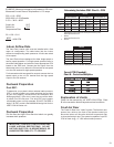
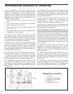
EXAMPLE: Airfl ow requirements are calculated as follows:
(Having a wet coil creates additional resistance to airfl ow.
This addit ional resistance must be taken into consideration
to obtain accurate airfl ow information.
1 ½ TON SYSTEM ( 18,000 Btu)
Operating on high speed @ 230 volts with dry coil
measured external static pressure .20
Air Flow = 500 CFM
In the same SYSTEM used in the previous example but
having a WET coil you must use a correction factor of
.94 (i.e. 500 x .94=470 CFM) to allow for the resistance
(internal) of the condensate on the coil.
It is important to use the proper procedure to check external
Static Pressure and determine actual airfl ow. Since in
the case of the VERT-I-PAK, the condensate will cause
a reduction in measured External Static Pressure for the
given airfl ow.
It is also important to remember that when dealing with
VERT-l-PAK units that the measured External Static
Pressure increases as the resistance is added externally
to the cabinet. Example: duct work, fi lters, grilles.
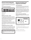
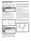
External Static Pressure
External Static Pressure can best be defi ned as the pressure
difference (drop) between the Positive Pressure (discharge)
and the Negative Pressure (intake) sides of the blower.
External Static Pressure is developed by the blower as a
result of resistance to airfl ow (Friction) in the air distribution
system EXTERNAL to the VERT-I-PAK cabinet.
Resistance applied externally to the VERT-I-PAK (i.e. duct
work, coils, fi lters, etc.) on either the supply or return side
of the system causes an INCREASE in External Static
Pressure accompanied by a REDUCTION in airfl ow.
External Static Pressure is affected by two (2) factors.
1. Resistance to Airfl ow as already explained.
2. Blower Speed. Changing to a higher or lower blower
speed will raise or lower the External Static Pressure
accordingly.
These affects must be understood and taken into consideration
when checking External Static Pressure/Airfl ow to insure that
the system is operating within design conditions.
Operating a system with insuffi cient or excessive airfl ow
can cause a variety of different operating problems.
Among these are reduced capacity, freezing evaporator
coils, premature compressor and/or heating component
failures. etc.
System airfl ow should always be verifi ed upon completion
of a new installation, or before a change-out, compressor
replacement, or in the case of heat strip failure to insure
that the failure was not caused by improper airfl ow.
Checking External Static Pressure
The airflow through the unit can be determined by
measuring the external static pressure of the system, and
consulting the blower performance data for the specifi c
VERT-I-PAK.
1. Set up to measure external static pressure at the
supply and return air.
2. Ensure the coil and fi lter are clean, and tha
t all the
registers are open.
3. Determine the external static pressure with the
blower operating.
4. Refer to the Air Flow Data for your VERT-I-PAK
system to fi nd the actual airfl ow for factory-selected
fan speeds.
5. If the actual airfl ow is either too high or too low, the
blower speed will need to be changed to appropriate
setting or the ductwork will need to be reassessed
and corrections made as required.
6. Select a speed, which most closely provides the
required airfl ow for the system.
7. Recheck the external static pressure with the
new speed. External static pressure (and actual
airfl ow) will have changed to a higher or lower value
depending upon speed selected. Recheck the a
ctual
airfl ow (at this "new" static pressure) to confi rm
speed selection.
8. Repeat steps 8 and 9 (if necessary) until proper
airfl ow has been obtained.
Checking Approximate Airfl ow
If an inclined manometer or Magnehelic gauge is not
available to check the External Static Pressure, or the
blower performance data is unavailable for your unit,
approximate air fl ow call be calculated by measuring the
temperature rise, then using tile following criteria.
KILOWATTS x 3413
= CFM
Temp Rise x 1.08
Electric Heat Strips
The approximate CFM actually being delivered can be
calculated by using the following formula:
DO NOT simply use the Kilowatt Rating of the heater (i.e.
2.5, 3.4, 5.0) as this will result in a less-than-correct airfl ow
calculation. Kilowatts may be calculated by multiplying
the measured voltage to the unit (heater) times the
measured current draw of all heaters (ONLY) in operation
to obtain watts. Kilowatts are than obtained by dividing
by 1000.