


2
secondary power lines; it is not effective against direct
hits.
6. Mount the control box in an area protected from rain,
snow, direct sunlight or other high temperatures as
this may cause tripping of the overload protector.
Also protect the control box from extreme cold (below
25
o
F/-32
o
C) as this may have adverse effects on
starting capacitor.
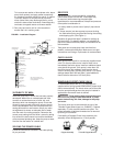
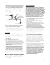
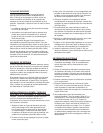
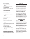
7. A two-wire pump does not require a motor control box,
since all electrical components are built inside the
motor. Fig. 2 shows a typical wiring diagram for a two-
wire installation.
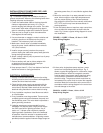
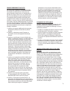
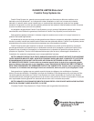
8. A three-wire, single-phase pump requires a motor
control box incorporating overload relays. Fig. 3
shows a typical wiring diagram for a three-wire, single-
phase installation. Note that a magnetic contactor
must be used if the pressure switch electrical rating
is not suffi cient to handle the submersible motor
electrical rating. The pressure switch would then be
incorporated into a pilot circuit to control the magnetic
contactor. Make the connections at the control box in
accordance with the wiring diagram in the control box
to avoid damage to the motor.
Incoming 1 Phase Power
1 Phase Submersible Motor
Submersible Cable
Pressure Switch
Circuit Breaker or
Fuse Disconnect Switch
FIGURE 2 - 2 WIRE, 1 Phase, 1/3 thru 1-1/2 HP
Pump Wiring Diagram
Circuit Breaker
or Fused Disconnect Switch
Pressure Switch (for pilot circuit)
If Magnetic Contactor is used
for starting.
Single Phase
Control Box
Red
Yellow
Black
1 Phase Sumbersible Motor
Pressure Switch (for direct switching) OR
Magnetic Contactor (w/ pilot circuit)
Incoming 1 Phase Power
Note: Order of red, yellow and black may
vary from control box to control box.
Always connect like colors.
L1
L2R
Y
B
FIGURE 3 - 3-WIRE, 1 Phase, 1/3 thru 15 HP
Pump Wiring Diagram
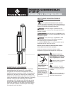
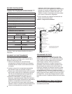
INSTALLATION OF PUMP, DROP PIPE, AND
ASSOCIATED EQUIPMENT
Fig. 1 illustrates a typical well installation showing in
ground components. Adhere to the following items when
installing the pump and drop pipe:
1. Fasten the submersible cable to the drop pipe with
clamps or appropriate tape every 10 ft. (3m) to
prevent tangling and damage to the cable. The cable
must remain slack when using plastic drop pipe to
allow for stretching of pipe when installed in the well.
2. Take care not to scrape or pinch the submersible
cable against the well casing.
3. Use an ohmmeter or megger to make insulation and
continuity checks on the cable once the pump is
installed. This locates any fault in the cable.
4. Make sure a check valve is installed immediately
above the pump. Install additional check valves at
100’ (30m) intervals.
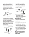
5. Install a torque arrestor just above the pump to
prevent chafi ng the cable when pump anad pipe twist
during starting and stopping.
6. Attach a safety cable to pump to prevent loss of pump
if pipe should break.
7. Place a sanitary well seal or pitless adapter with
an approved cover plate over top of well per
manufacturers recommendations.
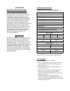
8. Keep pump at least 5’ (1.5m) from bottom of well and
above well screen or casing perforations.
ELECTRICAL INFORMATION
1. Employ a licensed electrician to perform the wiring.
All wiring must be done in accordance with applicable
national and local electrical codes.
2. Check that the power supply corresponds with the
electrical rating of the submersible motor and the
control box(if required). Make sure that the control box
electrical rating matches the motor electrical rating.
3. Every installation requires a fused disconnect switch
or circuit breaker.
4. Every installation must be grounded. There must be
a reliable ground connection between the pump and
the distribution panel. The motor lead incorporates a
green grounding conductor.
5. Lightning arrestors are recommended for every
installation. All stainless steel, single phase motors
thru 5HP have built-in lightning arrestors. Any 6”
motor or 4”, 3-phase motor requires a separate
lightning arrestor installed as close to the wellhead
as possible. Install the arrestor in accordance with
manufacturers recommendations. A lightning arrestor
provides protection against induced voltage surges on