


www.fmiproducts.com
55175G 9
FIREPLACE
INSTALLATION
Continued
GAS SUPPLY TESTING
Note: This section is intended as a guide for quali-
ed technicians installing gas to this appliance.
CAUTION: Do not connect
appliancebeforepressuretest-
inggaspiping.Damagetogas
valvemayresultandanunsafe
conditionmaybecaused.
The appliance and its individual shut-off valve
must be disconnected from the gas supply piping
system during any pressure testing of that system at
test pressures in excess of 1/2 psig (3.5 kPa).
The appliance must be isolated from the gas sup-
ply piping system by closing its individual manual
shut-off valve during any pressure testing of the
gas supply piping system at test pressures equal
to or less than 1/2 psig (3.5 kPa).
This unit has been tested for installation at high
altitude. Higher altitudes affect the atmospheric
pressure and heat valve of gaseous fuels. When
installing this unit at high altitudes, the rated
input will be lower than at sea level. The lowered
oxygen content in the air and the lowered gas
density require installation of a different size
orice in order to achieve clean combustion of
the unit. Consult the unit data plate for the proper
high-altitude orice size. Fill out the information
sticker attached to the unit when eld converting.
See Specications, page 15, when derating.
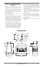
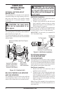
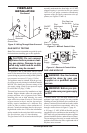
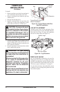
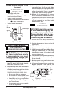
The gas control valve is secured to the burner pan
assembly underneath the front ledge. A 1/8" NPT
plugged tapping is provided on the gas control
valve for a test gauge connection immediately
upstream of the gas supply connection to the ap-
pliance (see Figures 13 and 14).
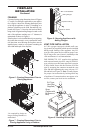
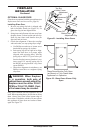
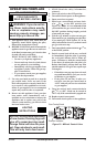
Figure 12 - Wiring Through Outer Surround
Figure 13 - Millivolt Control Valve
Figure 14 - Electronic Control Valve
ON/OFF
Knob
Pilot
Adjustment
Cap
Pilot Gas Line
Do Not Kink
Inlet
Pressure
Outlet
Pressure
To Main
Burner
To Pilot
Burner
E
A
From
Gas
Supply
To
Main
Burner
Inlet
Pressure
Outlet
Pressure
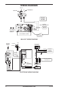
GAS LINE HOOK-UP
WARNING:Gaslinehookup
should be done by your gas
supplieror aqualiedservice
person.
WARNING: Before you pro-
ceed,makesureyourgassupply
is OFF.
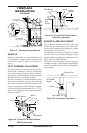
A manual shutoff valve has been included in the
appliance’s gas supply system. You may consider
installing an extra gas shutoff valve outside the ap-
pliance’s enclosure (check with local codes) where
it can be accessed more conveniently with a key
through a wall as shown in Figure 15, page 10.
A 30" long, 1/2" NPT SCHD 40 exible gas line
(supplied) may be used between the incoming 1/2"
NPT black iron gas line and the replace regulator
(located inside the rebox, under the access plate).
The incoming gas line may be routed toward the
appliance from either the left or right hand side of
replace outer surround.
Common
Ground Wire
Strain Relief
Grommet