


www.fmiproducts.com
55175G 11
FIREPLACE
INSTALLATION
Continued
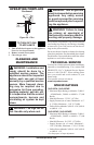
MANTELS
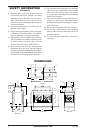
Mantels, combustible or non-combustible, may
be constructed as long as proper clearances are
observed (see Figure 5, page 6 and Clearances,
page 6).
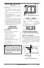
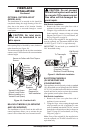
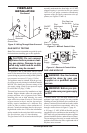
PILOT ASSEMBLY ADjUSTMENT
The pilot assembly is factory preset for the proper
ame height. Alteration to factory settings may
have occurred during shipping. If this is the case,
some minor readjustments may be necessary and
should be done by a qualied technician.
The pilot assembly is located behind the burner
next to the rear refractory piece at the right-hand
side. The thermopile (in millivolt models) or the
sensor (in electronic models) should be engulfed
with the pilot ame approximately 3/8" to 1/2" in
order for the regulator to receive proper signal (see
Figures 18 and 19).
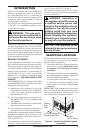
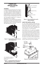
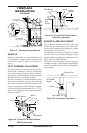
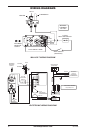
Figure 17 - Fireplace Facing Material
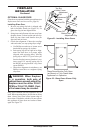
Figure 18 - Correct Pilot Flame Pattern -
Millivolt Assembly
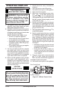
Figure 19 - Correct Pilot Flame Pattern -
Electronic Assembly
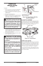
BURNER FLAME ADjUSTMENT
The air shutter, located at the base of the main
burner tube, has been factory preset to the proper
air to bas ratio which results in a long, blue, cleaner
burning ame (see Figure 20).
If readjustment is necessary, loosen the air shut-
ter screw and rotate air shutter until proper ame
setting is achieved, retighten air shutter screw. See
Figure 20 for air shutter location.
Closing the air shutter reduces the air-to-gas mix,
resulting in a longer, yellow ame which produces
excessive carbon monoxide (CO) and could also
cause sooting.
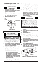
Figure 20 - Air Shutter Adjustment
Noncombustible
Facing Material
Do Not
Block
Effective
Opening
"L" Shaped
Metal Support
Noncombustible
Facing Material
Burner Pan
Air Shutter
Screw
Orice
Gas Valve
3/8" to 1/2"
1/8" to 1/4"
Pilot Burner
Ignitor
Flame
Sensor
Pan
Burner
3/8" to 1/2"
(10 mm - 13 mm)
1/8" (3 mm)
Ignitor
Pilot Burner
Thermopile