


www.fmiproducts.com
113084-01L12
INSTALLATION
Continued
* Purchase the optional equipment shutoff
valve from your dealer.
** Minimum inlet pressure for purpose of input
adjustment.
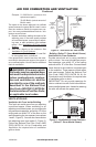
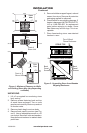
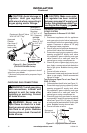
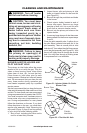
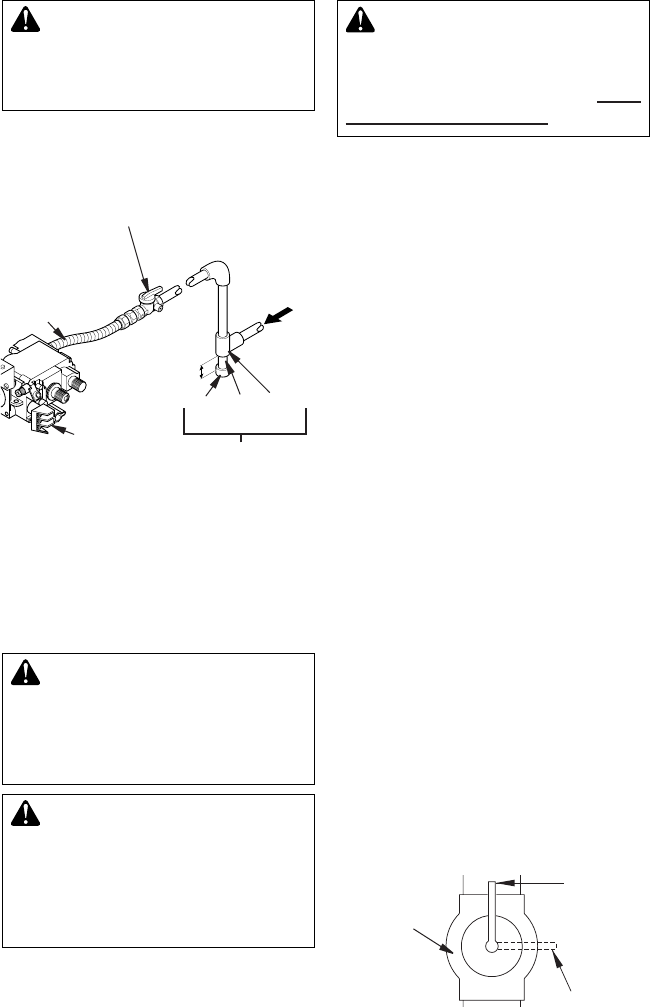
Figure 10 - Gas Connection
(SVYD18PRA/NRA Series)
3” Min
Sediment Trap
Gas Control
Equipment Shutoff Valve
With 1/8" NPT Tap*
Approved
Flexible
Gas Hose (if
allowed by
local codes)
Cap Pipe Tee
Nipple Joint
PROPANE/LP
From External
Regulator
(11" W.C. to 14"
W.C. Pressure)
NATURAL
From Gas
Meter (5" W.C.
to 10.5" W.C.
Pressure)
and connections, internal and
external to unit, for leaks after
WARNING: Never use an
-
CAUTION: Make sure exter-
Con-
necting to Gas Supply
PRESSURE TESTING GAS SUPPLY
PIPING SYSTEM
Test Pressures In Excess Of 1/2 PSIG
1. Disconnect appliance with its appliance
main gas valve (control valve) and equip-
ment shutoff valve from gas supply piping
system. Pressures in excess of 1/2 psig
will damage heater regulator.
2. Cap off open end of gas pipe where equip-
ment shutoff valve was connected.
3. Pressurize supply piping system by either
opening propane/LP supply tank valve
for propane/LP gas or opening main gas
valve located on or near gas meter for
natural gas or using compressed air.
4. Check all joints of gas supply piping sys-
tem. Apply a noncorrosive leak detection
uid to gas joints. Bubbles forming show
a leak.
5. Correct all leaks at once.
6. Reconnect heater and equipment shutoff
valve to gas supply. Check reconnected
ttings for leaks.
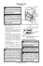
1.
Close equipment shutoff valve (see Figure 11).
2. Pressurize supply piping system by either
opening propane/LP supply tank valve
for propane/LP gas or opening main gas
valve located on or near gas meter for
natural gas or using compressed air.
3. Check all joints from gas meter for natural
or propane/LP supply to equipment shutoff
valve (see Figure 12 or 13, page 13). Apply
a noncorrosive leak detection uid to gas
joints. Bubbles forming show a leak.
4. Correct all leaks at once.
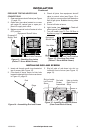
Figure 11 - Equipment Shutoff Valve
Equipment
Shutoff Valve
Closed
Open