


www.fmiproducts.com
124386-01A6
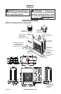
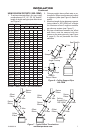
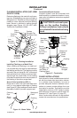
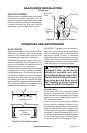
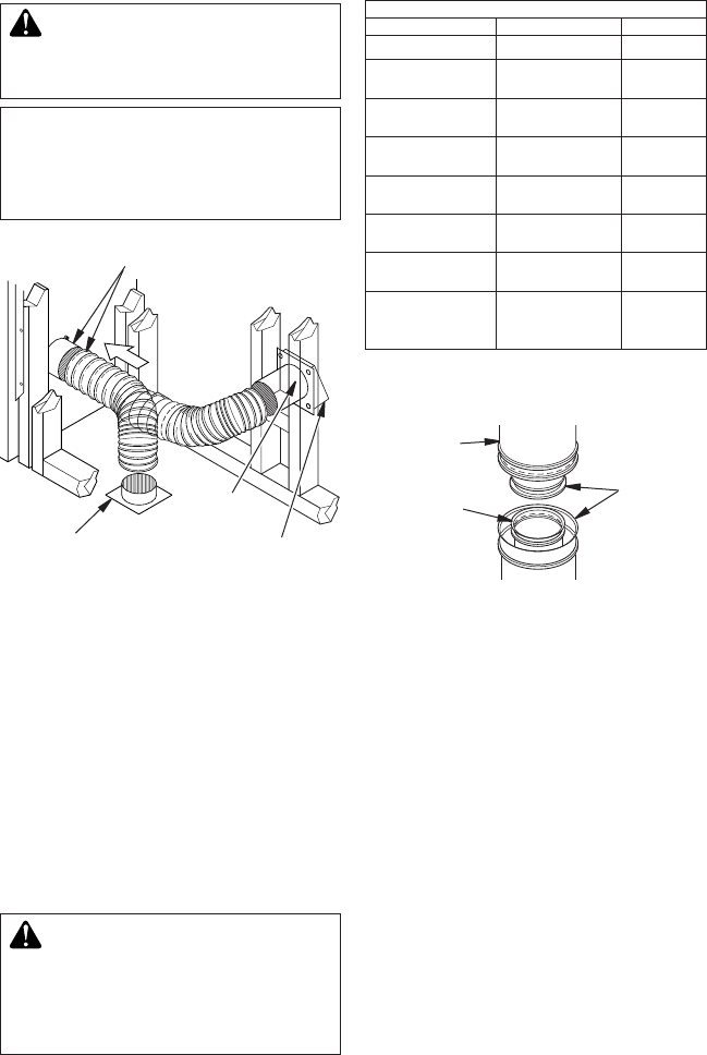
Figure 6 - Lineal Gain
LINEAL GAIN
PART NO. DESCRIPTION GAIN (IN)
48" Plantation Fireplace 66
1
/
2
"
12-12DM
12-12HT
Pipe Section 10
5
/
8
"
18-12DM
18-12HT
Pipe Section 16
5
/
8
"
24-12DM
24-12HT
Pipe Section 23
5
/
8
"
36-12DM
36-12HT
Pipe Section 34
5
/
8
"
48-12DM
48-12HT
Pipe Section 46
5
/
8
"
RLT-12D
RLT-12HT
Round
Termination
7
3
/
4
"
*
STL-12D
Square Chase-
Top with Slip
Section
7
"
to 15
"
*
* The lineal gain for the terminations is mea-
sured to the ue gas outlet height.
Hemmed
End
12
3
/
8
"
Stainless
Inner Pipe
15" Galvanized
Outer Pipe
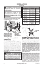
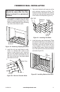
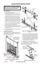
ASSEMBLY AND INSTALLATION OF
DOUBLE WALL CHIMNEY SYSTEM
Each double wall chimney section consists of
a galvanized outer pipe, a stainless steel in-
ner ue pipe and a wire spacer. Pipe sections
must be assembled independently as chimney
is installed. When connecting chimney directly
to replace, inner ue pipe section must be
installed rst with lanced side up. Outer pipe
section can then be installed over ue pipe
section with hemmed end up. Press down
on each pipe section until lances securely
engage hem on replace starter. Wire will
assure proper spacing between inner and
outer pipe sections.
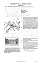
Continue to assemble chimney sections as
outlined above, making sure both inner and
outer pipe sections are locked together. When
installing double wall snap-lock chimney to-
gether, it is important to assure joint between
chimney sections is locked. Check by pulling
chimney upward after locking. Chimney will
not come apart if properly locked. It is not
necessary to add screws to keep chimney
together (exception, see Figure 9, page 8).
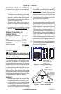
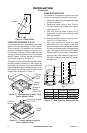
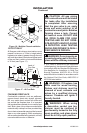
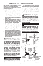
Figure 5 - Outside Air Kit
Secure to Collars with Metal Tape, Screws
or Straps (Min. of 1/4" x 20" in size)
Air Inlet
Location
Must Allow
For Bushes
or Snow
Vent Hood
Required for
Wall Installation
Air Inlet
Eyebrow
Vented Crawl Space
(Check Local Codes
Before Installing in a
Vented Crawl Space)
CAUTION: Combustion air
inlet ducts shall not terminate
in attic space.
The maximum height for the
air vent can not exceed 3 feet
below the ue gas outlet of the
termination.
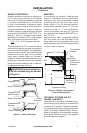
CHIMNEY PIPE
FMI PRODUCTS, LLC chimney system
consists of 12", 18", 24", 36"' and 48" snap-
lock, double-wall pipe segments, planned
for maximum adaptability to individual site
requirements. Actual lengths gained after t-
ting overlaps must be taken into consideration
(lineal gain) and are given in lineal gain chart
(see Figure 6). Lineal gain is the actual mea-
surable length of a part after two or more parts
are connected. For Canada, use chimney parts
designated "HT".
WARNING: The opening in the
collar around the chimney at the
top of the replace must not be
obstructed. Never use blown insula-
tion to ll the chimney enclosure.
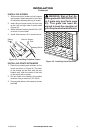
INSTALLATION
Continued