


6
CG913TM only
The operation of the appliance, including
the ignition system, must be tested
before installation is complete.
If after following the instructions given,
satisfactory performance cannot be
obtained, contact the local gas authority
or your local Approved Service Agent for
advice and assistance.
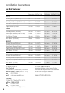
Conversion to Different Gas Type
Burners can be used with NG or LPG,
provided that the orifices appropriate for the
gas supply are installed.
To change the orifices, you will need a 7 mm
box spanner (and a 10 mm ring spanner for
CG913TM).
1
Turn off the main electrical supply.
WARNING!
Electrical Shock Hazard.
Disconnect product from main power
supply before continuing.
2
Ensure all gas valves are turned off.
3
Remove all trivets and burner heads.
4
Pull off knobs.
5
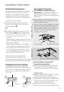
Unscrew the orifices and replace them
with the correct ones. (size numbers are
stamped on the side, eg. 70= 0.70 mm)
(see figure 1)
6
Remove the 2 screws holding each burner
(3 on the wok burner).
7
Lift hob tray from the product.
WARNING!
Cut Hazard.
Beware of sharp edges.
8
Replace the wok orifice with the correct
one using a 10 mm spanner.
9
Reset the venturi (see fig.2). Loosen the
venturi screw, move the venturi toward the
orifice approx. 2 mm.
10
To refit the CG913 series hob tray, repeat
steps 6 and 7 in reverse.
11
Check insulation resistance and earth
continuity.
Natural Gas
For Natural Gas usage the gas supply is
connected to the regulator which is supplied
loose with a built in test point - 1kPa (4” WG)
and the inlet connection of 1/2 “ B.S.P. (male
thread). Do not over tighten.
The test point pressure should be preset
to 1.0 kPa with the wok and semi - rapid
burners operating at maximum.
LP Gas
For LPG usage the gas supply for the
appliance must be regulated to a pressure
of 2.75kPa (11” WG). See ‘Conversion to a
different gas type’ .
Gas Supply Connection Check
The connection point shall be accessible
with the appliance installed.
To enable the gas supply to be readily shut
off, the gas supply must be connected with
an isolating valve close to the product.
After installation and making all connections
check thoroughly for possible leaks.
1
Turn all control knobs on the unit to “off”
position.
2
Open the valve on the gas supply.
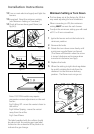
3
Using a suitable leak detection fluid solution
(e.g. Rocol) check each gas connection one
at a time by brushing the solution over the
connection.
4
The presence of bubbles will indicate a leak.
Tighten the fitting and recheck for leaks.
Ensure the washer (supplied) is located
between elbow and product gas inlet.
5
Turn on each gas valve and light each
burner.
6
Check for a clear blue flame without yellow
tipping. If burners show any abnormalities,
check that they are located and assembled
properly. Check correct orifices are installed.
Installation Instructions
continued...