Page 6
5. Remove lamp carefully, by sliding the lamp to the left through the hole on the left side of the chamber. After
exposing the connection end of the lamp inside the chamber, remove the lamp through the front of the unit.
NOTE: When replacing the lamp, always wipe off lamp with the supplied alcohol wipe after installing.
6. Replace the lamp by first guiding the end of the lamp through the hole on the left side of the UV chamber.
Next, guide the other end of the lamp through the hole on the right side of the UV chamber. Hold the lamp in
position while rotating the swivel bracket into position. Secure the lamp into position by tightening the wing
nut onto the swivel bracket.
NOTE: UV lamps contain a small amount of mercury, like a typical fluorescent lamp. Check with your local waste
management authority for local disposal or recycling requirements. According to the EPA’s Universal Waste
Rule, these types of lamps may be disposed of into household waste.
7. Close the Chamber access door and rotate the door clips to secure the door into position.
WARNING: Never expose eyes or skin to UVC light from any source. Looking directly at the UVC light may cause
permanent eye damage or blindness.
8. Plug the power cord back into the wall receptacle or restore power to the UV-
1500C circuit.
9. Turn the knob on the speed control to the on position, press the door switch in,
and allow the motor to start and the lamp to light. Wait 30 seconds.
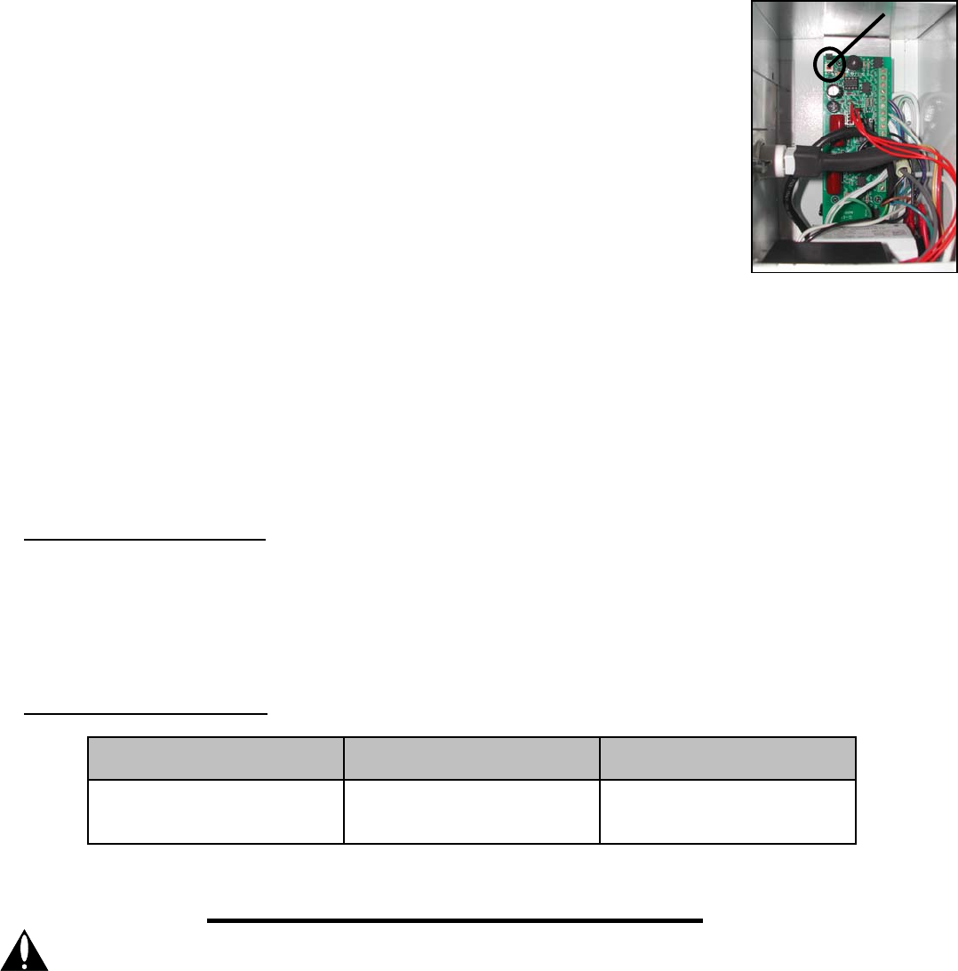
10. Reset the lamp timer by using the eraser end of a pencil or the blunt end of a
plastic ink pen and press and hold the timer-reset button on the circuit board for
30-45 seconds (See Figure 21). After releasing the timer-reset button the LED on
the front of the unit will flash twice indicating the timing circuit has been reset.
11. Release the door switch, turn the knob on the speed control to the off position and
close the front cover of the unit. Secure the cover with the door mounting screws.
12. Turn the speed control knob clockwise to turn on the unit and adjust the motor/fan
speed control to the desired airflow. After the fan has started the LED light will
show a continuous “GREEN” color indicating proper unit operation
R
EPLACING AIR FILTERS
1. Loosen the two door-mounting screws on front cover of the UV-1500C. Open the cover to expose the filters
and the air purification chamber. (See Figure 17)
2. Replace the 12” by 12” air filter by removing the filter and replacing the filter with the wire support side of the
filter installed toward the fan intake of the unit. (See Figure 18)
3. Replace the carbon filter by removing the old filter and inserting the new filter back into the filter holder being
sure safety switch is depressed.
VII. TROUBLESHOOTING GUIDE
1. If the LED is illuminating a “YELLOW” color and the circuit board alarm beeps every 15 minutes, then the lamp
should be replaced soon.
2. If the LED is illuminating a “RED” color and the circuit board alarm beeps every 5 minutes, then the lamp should
be replaced.
3. If lamp does not light up 1) be sure the safety switch located in the carbon filter chamber is depressed with
pressure from the filter or 2) replace lamp.
4. If lamp still does not light up after checking the safety switch or replacing the lamp, replace ballast.
VIII. REPLACEMENT PARTS LIST
LAMP BALLAST
YEARLY FILTER AND
LAMP REPLACEMENT KIT
(Field Controls Part Number)
46365401
(Field Controls Part Number)
46365514
(Field Controls Part Number)
46453600
For replacement parts, contact your local heating service company. Any questions, please contact Field Controls at:
Phone: 252-522-3031 Fax: 252-522-0214 Email: sales@fieldcontrols.com
WARNING: Never expose eyes or skin to UVC light from any source. Looking directly at the UVC light may cause permanent eye damage o
r
blindness. Never operate the UV-Aire™ Air Purifying System with the UV chamber door open. Avoid touching the glass portion of the
lamp with your hands.
Figure 21
Reset
Button


