Page 5
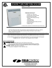
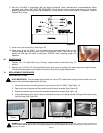
Figure 16
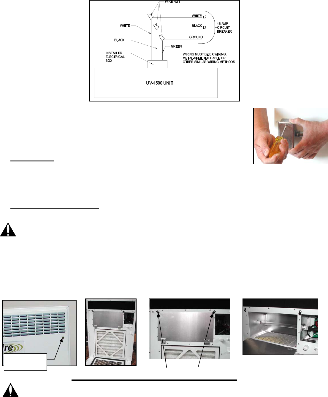
11. Wire the UV-1500C in accordance with the National Electrical Code, manufacturer's recommendations and/or
applicable local codes. UNIT MUST BE GROUNDED. Check ground circuit to make certain that the unit has been
properly grounded. The wiring should be protected by an over current circuit device rated at 15 amperes. Refer to
Diagram A for wiring.
11. Place cover over conduit box. (See Figure 16)
12. Apply power to the UV-1500C. Turn the speed control knob clockwise to turn on the
unit and adjust the motor/fan speed control to the desired airflow. After the fan has
started the LED light will show a continuous “GREEN” color indicating proper unit
operation.
VII. MAINTENANCE
1. Replace 12”x 12” intake filter every 90 days, replace carbon outlet filter every 12
months.
2. Replace your UV-Aire™ Air Purifying System lamp once a year to maintain the lamps maximum output intensity.
The lamp should operate continuously for maximum lamp life and light effectiveness.
VI. REPLACEMENT PROCEDURES
R
EPLACING THE UV LAMP
VERY IMPORTANT: Turn the speed control switch on unit to ‘OFF’ position and unplug unit from outlet or turn off
power to the unit before replacing the UV lamp.
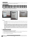
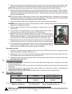
1. Loosen the two door-mounting screws on front cover of the UV-1500C. (See Figure 17)
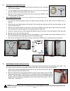
2. Open the cover to expose the filters and the air purification chamber (See Figure 18).
3. Rotate the two door clips to allow the chamber access door to open (See Figure 19).
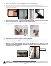
4. Unplug ballast plug from end of lamp and loosen the wing nut on swivel bracket. Swing swivel bracket away
from the lamp (See Figure 20).
Diagram
A
Figure 17
Figure 18
Figure 19
Door Clips
Figure 20
WARNING: Never expose eyes or skin to UVC light from any source. Looking directly at the UVC light may cause permanent eye damage o
r
blindness. Never operate the UV-Aire™ Air Purifying System with the UV chamber door open. Avoid touching the glass portion of the
lamp with your hands.
Door Mounting
Screw


