


It is recommended that humidistat settings of 30-45% not be
exceeded. If condensation is noticed on windows during very
cold outside temperatures, the humidistat setting should be
lowered.
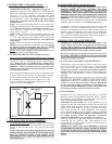
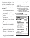
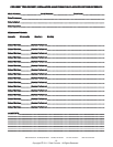
RELATIVE HUMIDITY CHART
The maximum recommended relative humidity for your
home depends upon many factors such as outdoor air
temperature, type and placement of insulation, vapor
barriers, effectiveness of weather stripping, type of windows
and doors (including frames and jambs) and whether or not
storm windows and doors are used. With all these variables it
is nearly impossible to recommend a proper humidity
setting. The best humidistat setting is one that you are most
comfortable with. Also, as the outdoor temperature
fluctuates, it may be necessary to adjust the humidity level of
your system a few times during the heating season.
Refer to the "Relative Humidity Chart" as a starting point for
your proper humidistat setting. Generally, in a tighter and
better insulated house, the humidistat may be set higher than
in a drafty, un-insulated house.
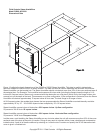
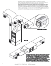
IMPORTANT: If the humidifier is installed in the return air
plenum the humidistat must be located at least five (5) feet
upstream from the humidifier. Fan should be operated in
continuos mode when the humidistat is mounted in the return
air plenum. Mounting the humidistat on an interior wall is
always preferable to mounting on the return duct. But
mounting the humidistat on an interior wall takes more time,
material and labor than a return duct location. Sometimes it
may be impossible to mount a humidistat on an interior wall
and the return duct location is the only solution.
Installation instructions for the 072000 model
Humidistat are packaged with the 072000.
Your humidifier may include Model 062000 Humidistat.
Installation instructions for the 062000 model are packaged
with the 062000.
There are many ways to wire and control a humidifier. Refer
to the wiring diagrams on pages 4 and 7.
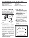
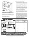
10. SETTING THE HUMIDISTAT
R
H
O
D
%
R
H
T
EM
P
M
A
N
A
U
T
O
M
O
D
E
Outside
Dry Bulb
Temperature
Recommended Indoor
Relative Humidity
Setting
0 Deg. F
20 Deg. F
30 Deg. F
35 Deg. F
and up
10 Deg. F
15%
20%
25%
35%
40-45%
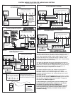
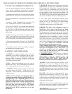
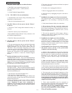
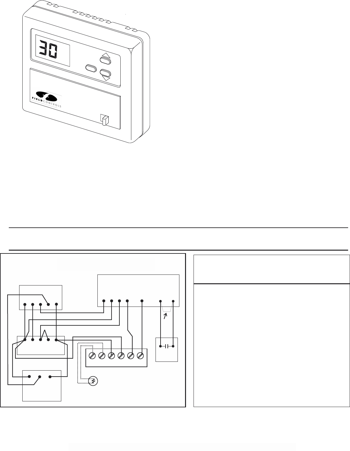
Variable Speed WIRING DIAGRAM
FIG. 15
Variable Speed Furnace
G1 R G2 H H
Typical Thermostat
G YWR
G YWR
Variable Speed Heat & Cool System and
A
A
S2000 & S2020 Humidifier
Low Voltage Terminal Block
REMOVE
FACTORY
JUMPER
C
C
OD OD C
R
H
H
Outdoor
Temperature
Sensor
072000 Humidistat
Y
C
Hi-Efficiency
Condensing
Unit
R
7
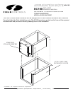
Figure 14.
The diagram above should be followed if it is required to operate the fan system at high speed during the humidify operation. Such a
requirement may be necessary if condensation occurs inside the duct-work due to the lower velocities of a variable speed system
when only the fan is running. The “Y” circuit must be wired exactly as shown to achieve the correct operation. This wiring configuration may
result in the loss of the “enhanced” latent effect operations of your variable speed HVAC system. If you do not want this to happen, you
should consider installing a different type of whole house humidifier that does not require dominance over the HVAC fan and full CFM
capacities while operating. Variations on this diagram are available. Contact EWC Controls Technical Support Hotline.
Model APD or
Equivalent
Copyright © 2011 Field Controls All Rights Reserved.
Steam Humidifier with 072000 Humidistat
Variable Speed Heat & Cool System and
Steam Humidifier with 072000 Humidistat
Variations on this diagram are available. Contact Field Controls Technical Support Hotline.