


6. WATER SUPPLY - Required Criteria
9. WIRING THE STEAM HUMIDIFIER
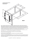
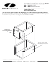
7. M OUNTING THE STEAM HUMIDIFIER
8. STEAM OPERATION - Required Criteria
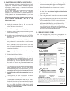
A. WATER SUPPLY USING THE SADDLE VALVE
FURNISHED WITH UNIT. Important! See page 14.
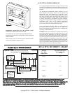
A. INSTALLING AND WIRING THE HUMIDISTAT
B. OVERFLOW & DRAIN LINES - Required Criteria
Installation instructions for the saddle valve are printed on the
plastic bag containing the saddle valve and its components.
Tap into a 1/2” or 3/4” domestic cold water line. Avoid
connecting to water lines from a Reverse Osmosis system or
De-ionized water systems. The supply water must read a
minimum of 25 ppm in order for the Steam unit to reliably
sense the water.
NOTE: Never install the saddle valve on the bottom of the
water pipe. Sediment in the water pipe may clog the saddle
valve. Flush the line before connecting to the unit.
tightening the hex compression nut, tighten only enough to
assure there are no leaks.
NOTE: Saddle valves do not meet plumbing codes in some
areas. A “T” fitting with a valve may be required to meet code
or, if low water pressure causes frequent water alerts on the
steam humidifier. NOTE: Flush the new water line before
connecting it.
NOTE: The use of City water or Municipal water is preferred.
Softened water is preferred over untreated well water. Specify
the Optional WFA-195 disposable water filter for treating
any water supply that is very high in mineral content.
NOTE: Use a water hammer arrester (WH-100) if water
spikes occur (pipes bang)during fill ups.
When
A temperature sensor is mounted in the water reservoir of the
humidifier. As the water temperature increases to about 170
degrees F, the computer closes a set of blower relay contacts to
start the system fan. When the water cools to about 140 degrees
F, the computer will open the relay contacts to shut off the fan.
This operational sequence drastically decreases the chances of
condensation occurring inside the duct-work.
A humidistat, such as the Model #072000 is required to control
the Steam Humidifier. The humidistat may be installed on the
wall in the living space or on the return air duct. NOTE:
Continuos fan operation should be initiated if the humidistat is
installed on the return air duct! Instructions for installation are
packaged with each humidistat. Follow wiring instructions
carefully!
DO NOT connect any foreign voltage to the “H” terminals of the
humidifier! The Humidifier supplies it’s own control voltage.
Simply connect the two “H” terminals straight to any dry contact
humidistat terminals. If you are using a 3rd party Humidistat
that has powered terminals, you must use an isolating relay
to operate the Steam Humidifier. Failure to do so will result
in circuit board failure and will void all warranties.
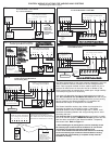
Schematics on the following pages describe the suggested
interlock wiring arrangement for different HVAC systems.
Interlocking may be performed on systems that provide a 24vac
NEC Class 2 terminal block for system control.
AIR PROVING FEATURE: The Steam Humidifier has an
integrated air proving feature that allows the user to install a sail
switch and/or high humidity switch in the duct and easily
achieve fail safe shutdown in the event of fan/blower failure.
This feature prevents the Steam Humidifier from operating
unless adequate airflow is proven thereby avoiding a saturated
duct condition. WARNING: It is highly recommended to use
an airflow proving device. In particular Duct-Board
applications should always use an airflow proving device.
A factory jumper wire is provided and must be removed when
connecting the sail switch or other field supplied air flow
proving device. Leave the jumper in place if you decide not to
use the airflow proving feature.
IMPORTANT NOTE: If the Steam Humidifier is removed
and disconnected from the system, the blower interlock
circuit must be restored to it's original configuration. Failure
to do so may result in loss of blower operation during cooling
modes!
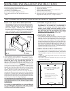
Use gasket material to seal where the front plate or tank flange
contacts the duct-work. Place the humidifier reservoir into the
opening in the duct and secure with eight (8) sheet metal
screws.
NOTE: If the duct-work will not support the unit in a level
position with the water pan full of water, the duct-work
must be reinforced. Both steam models weigh
approximately 9 Lbs. empty and approximately 15 Lbs.
when full of water.
Because of the high output of this Humidifier, it must not be
operated without the blower operating. The steam
humidifier is designed to be "Dominant" over the HVAC
System Blower. The "System" Blower will be operated by the
humidifier when the water tank temperature reaches 170
degrees F. A minimum of 800 cfm @ 800-900 fpm is required for
proper operation of the steam humidifier. Lower velocities may
result in excessive condensation inside the duct. See Air Proving
Feature on the next column! See Variable Speed on Page 7.
The use of an overflow line and drain line is always required.
Use the supplied 1/2” ID high temperature hose. Slip the hose
over the 1/2” OD “T” drain fitting and use a hose clamp to
secure. Route the hose to a suitable drain, avoiding kinks,
traps and sharp objects. DO NOT route the hose above the
humidifier. Failure to install all necessary drain lines may
result in water leaks during normal operating conditions,
and voids all warranties.
3
B. FIELD WIRING
IMPORTANT: Dedicated fused circuits and outlets of the
proper voltage and current ratings must be provided. Use a
NEMA 5-20R receptacle for the S2000 and a NEMA 6-15R
receptacle for the S2020. All wiring must conform to local and
national codes. Failure to do so will void all warranties.
DO NOT cut off the grounded plug and/or hard wire this unit to
line voltage! DO NOT use extension cords to operate this unit!
Doing so will void all warranties.
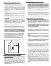
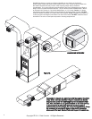
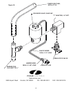
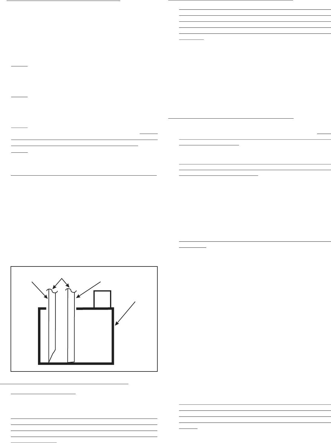
When routing the S2000 drain hose into a condensate pump,
be sure to cut the end of the hose at a sharp angle to prevent
the hose from bottoming out in the pan. It could result in
poor draining or no draining at all. Failure to do so may
result in water backing up into the S2000 reservoir and
eventual overflow. See Figure 5.
CORRECT
INCORRECT
X
CONDENSATE
PUMP
DRAIN
HOSE
FIG. 5