


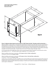
Typi cal
Furnace
S2000 & S2020 Humidifier
Low Voltage Terminal Block
G1 R G2 H H
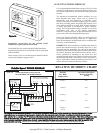
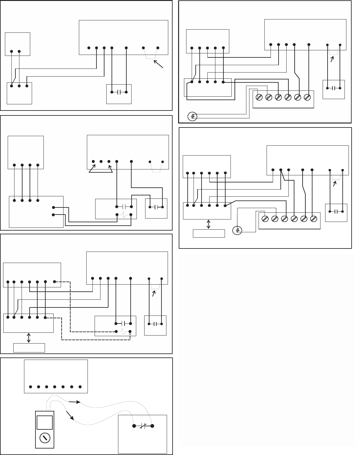
Heat only
Thermostat
WR
GWR
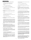
Heat Only System and
Steam Humidifier with standard
dry contact Humidistat
Dry Contact
Humidistat
A
A
FIG. 6
Factory
Jumper will
stay in place
unless a field
installed Air
Proving Device
is used.
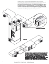
FIG. 8
Bryant Evolution
Furnace
SPST Dry Contact
Isolating Relay
with 24vac Coil
G1 R G2 H H
C DBA
C DBA
Bryant/Carrier Evolution/Infinity
Variable Speed Heat/Cool System
A
A
Model APD or
Equivalent
S2000 & S2020 Humidifier
Low Voltage Terminal Block
24vac
Common
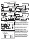
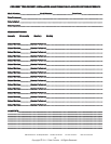
CONTROL WIRING SOLUTIONS FOR VARIOUS HVAC SYSTEMS
Additional diagram shown on page 7.
blower on the HVAC system does not operate when called
operating the blower on the HVAC system. If the Steam
Humidifier detects a loss of airflow longer than 1 minute, it will
shutdown the heating element and stop producing steam to
across the normally open contacts with the fan/blower running.
fan/blower is running.
062000 Humidistat
G1 R G2 H H
A
A
S2000 & S2020 Humidifier
Low Voltage Terminal Block
Disconnect the wires from the “A”
terminals and check the device & circuit
with a reliable ohm meter. Check continuity
when the fan is off and when it is running.
Model APD current
sensing switch or
equivalent air proving
device. Dry Contacts Close
when fan is running!
00.3
OHM
FIG. 11
4
FIG. 7
Typical Furnace
G1 R G2 H H
Typical Thermostat
G YWR
G YWR
A
A
S2000 & S2020 Humidifier
Low Voltage Terminal Block
REMOVE
FACTORY
JUMPER
C
C
OD OD C
R
H
H
Outdoor
Temperature
Sensor
072000 Humidistat
Refer to the 072000 Technical Bulletin
Model APD or
Equivalent
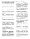
FIG. 10
Typical Air Handler
G1 R G2 H H
Thermostat with built-in
Humidification Control
G Y
W2
R
G Y
W2
R
Heat Pump System and Steam Humidifier with
Combo Thermostat/Humidistat
and Isolating Relay
A
A
S2000 & S2020 Humidifier
Low Voltage Terminal Block
REMOVE
FACTORY
JUMPER
C
HC
O
O
Outdoor Heat Pump
not shown for clarity
SPST Dry Contact
Isolating Relay
with 24vac Coil
Model APD or
Equivalent
HUM
Bryant
Evolution
Thermostat
DO NOT USE
Program Evolution
T-stat as follows:
1.Heating airflow
To Efficiency mode.
2.Humidifer
installed=Yes
3.Humidify with
Fan=Yes
4. Set FAN to
Continuous Mode &
select MEDIUM
speed.
NOTE: An APD or similar device
must be used in this application.
Wire the APD in series with the HH
circuit.
OD OD C
R
H
H
Outdoor
Temperature
Sensor
072000 Humidistat
Refer to the 072000 Technical Bulletin
FIG. 9
Typical Air Handler
G1 R G2 H H
Typical Heat Pump
Thermostat
G Y
W2
R
G Y
W2
R
A
A
S2000 & S2020 Humidifier
Low Voltage Terminal Block
REMOVE
FACTORY
JUMPER
C
C
O
O
Outdoor Heat Pump
not shown for clarity
Model APD or
Equivalent
Leave Factory
Jumper in Place
Conventional Heat & Cool System
and Steam Humidifier with 072000
with 072000 Humidistat
Heat Pump System and Steam Humidifier
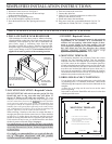
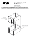
The latest improvement to the Field Controls humidifiers is the new
“Airflow Interlock Feature” provided on the low voltage terminal
block. Due to popular demand we have made it easier for you to
achieve fail safe lockout in the event the fan or blower on the
HVAC system does not operate when called upon. A high humidity
or airflow proving device is necessary.
You must still determine the type of proving device you want to
use. We recommend our new Model APD switch. But then all you
have to do is connect two low voltage wires from your air proving
device straight to the Steam Humidifier’s “A” terminals. No
additional field relays or components are needed.
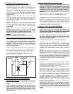
The Steam Humidifier monitors the airflow circuit anytime it is
operating the blower on the HVAC system. If the Steam
Humidifier detects a loss of airflow longer than 1 minute, it will
shutdown the heating element and stop producing eam to avoid
saturating the duct.
You must test the air proving device when you install it to make
sure it will function properly. WARNING: DO NOT perform this test
with the wires connected to the Steam Humidifier. Temporarily
disconnect them. Refer to Figure 11.
1. After installing the air proving device, test for continuity across
the normally open contacts with the fan/blower off. You should
read infinity (no continuity) when the fan/blower is off.
2. Turn on the fan/blower at the thermostat and test for continuity
across the normally open contacts with the fan/blower running.
You should now read continuity (a complete circuit) when the
fan/blower is running.