


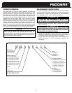

Model
5
FINAL CHECKS FOR INSTALLER
1. Ensure that all wiring is routed away from tubing and sheet
metal edges to prevent rub-through or wire pinching.
2
. Ensure that all wiring and tubing is secure in unit before
adding panels and covers.
3. Tighten service valve stem caps to 1/12 turn past
finger tight.
4. Leave this manual with owner. Explain system operation
and periodic maintenance requirements outlined in manual.
COOLING OPERATION
T
urn the thermostat heat/cool switch to the cool position.
Set the desired temperature on the thermostat dial. Do not
operate the cooling unit for extended periods at indoor
temperatures over 85°F. The unit indoor design temperature
range is between 70°F and 80°F in the cooling mode.
It is not recommended to vary the temperature settings
more than 5°F. Varying the temperature more than 5
degrees or turning the thermostat off for periods less than
12 hours can actually cost you more in energy consumption
than keeping the temperature constant. Consider indoor
plants and pets when varying the temperature from the
normal comfort level.
HEATING OPERATION
Turn the thermostat heat/cool switch to the heat position.
Set the desired temperature on the thermostat dial. Do not
operate the heating unit at indoor temperatures over 80°F.
The unit indoor design temperature range is between 65°F
and 80°F in the heating mode.
Never operate the unit in the cooling mode at outdoor
temperatures below 60°F without a low ambient control.
Never operate the unit in the heating mode at outdoor
temperatures above 70°F.
Auxiliary heat
Most heat pump installations include electric resistance heat
for auxiliary heat (when the outdoor temperature is too low
for the heat pump to provide enough heat) and for
emergency heat (the outdoor unit is not working). On a
properly-sized installation the heat pump will supply all the
heat needed during cool weather. As the temperature drops,
the heat output from the heat pump will be reduced. The
auxiliary heat installed in the system will come on as needed
to make up for this reduction of heat output.
The need for auxiliary heat is detected by the thermostat. If
the thermostat senses a temperature fall of more than 2°F
below the set point, the auxiliary heat will turn on. For this
reason, setting the thermostat to the desired temperature
and not changing the temperature during the day can be
more economical than varying the thermostat setting.
If it is intended to set the temperature back at night,
consider that, when the temperature is turned back up to
the normal setting, the system will be operating during the
coldest time of the day (early morning hours) and may
require auxiliary heat if the increase in temperature is above 2
°
F.
Emergency heat
This switch will turn the outdoor unit off and use the electric
auxiliary heat only to provide heat. If outdoor unit should
malfunction, turn the emergency heat switch to the ON
position and contact your service person.
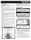
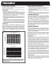
SUB-COOLING CHARGING
For proper sub-cooling readings, a standard high side gauge is
required for pressure readings.
U
se the charts below to determine the required sub-cooling value.
INSTRUCTIONS
1. Measure the outdoor air temperature. (T1)
2. Measure the liquid line pressure and determine the liquid
refrigerant temperature by the scale on the high side
pressure gauge. (T2) In cooling mode take reading at the
indoor coil before TXV. In heating mode take reading at the
l
iquid line service valve on outdoor unit.
3. Measure the liquid line temperature on the liquid line. (T3) In
cooling mode take reading at the indoor coil before TXV. In
heating mode take reading at the liquid line service valve on
outdoor unit.
4. Subtract T3 from T2. (T2 – T3) This is the subcooling value.
Compare this value and the outdoor temperature (T1), to the
charts below. If the value is below the line, add refrigerant. If
the value is above the line, remove refrigerant charge. When
removing refrigerant, always use standard reclaim procedures.
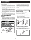
Adjusting TXV
For the majority of installations no adjustment to the TXV
setting is required. However, if the measured superheat at the
indoor coil is less than 4° or greater than 8° an adjustment is
required. The adjustment stem is at the base of the valve under
the flare nut. To increase superheat, tighten the stem clockwise
and to decrease superheat, back-out the stem counter-
clockwise. Use a 1/4” refrigeration service wrench for this
function.
37
35
33
31
29
27
25
23
21
OUTDOOR TEMPERATURE °F (T1)
OUTDOOR TEMPERATURE
°F (T1)
HEATING MODE
COOLING MODE
SUBCOOLING (T2-T3)
SUBCOOLING (T2-T3)
°F °F °F °F °F °F
4
6
8
10
12
SUB-COOLING CHARTS FOR UNITS WITH TXV
All values are for reference only and may vary up or down.
All heating values ar
e with fr
ost-fr
ee outdoor coil. When the
outdoor temperatur
e is below 40°F manually defrost the
unit before reading.
119