


RC4194 PRODUCT SPECIFICATION
9
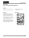
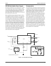
If a small signal silicon diode is used, it will clamp the nega-
tive output voltage at about +0.55V. A Schottky barrier or
germanium device would clamp the voltage at about +0.3V.
Another cure which will keep the negative output negative at
all times is the 1 mW resistor connected between the +15V
output and the Comp- terminal. This resistor will then sup-
ply drive to the negative output transistor, causing it to satu-
rate to -1V during the brownout.
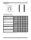
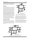
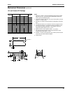
Heatsinking
Voltage Regulators are power devices which are used in a
wide range of applications.
When operating these devices near their extremes of load
current, ambient temperature and input-output differential,
consideration of package dissipation becomes important to
avoid thermal shutdown at 175°C. The RC4194 has this fea-
ture to prevent damage to the device. It typically starts
affecting load regulation approximately 2°C below 175°C.
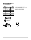
To avoid shutdown, some form of heatsinking should be used
or one of the above operating conditions would need to be
derated.*
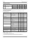
The following is the basic equation for junction temperature:
Equation 1
where
T
J
= junction temperature (°C)
T
A
= ambient air temperature (°C)
P
D
= power dissipated by device (W)
q
J-A
= thermal resistance from junction to ambient
air (°C/W)
The power dissipated by the voltage regulator can be detailed
as follows:
Equation 2
where
V
IN
= input voltage
V
OUT
= regulated output voltage
I
O
= load current
I
Q
= quiescent current drain
T
J
T
A
P
D
q
JA–
+=
P
D
V
IN
V
OUT
–()I
O
V
IN
I
Q
´+´=
Let’s look at an application where a user is trying to deter-
mine whether the RC4194 in a high temperature environ-
ment will need a heatsink.
Given:
T
J
at thermal shutdown = 150°C
T
A
= 125°C
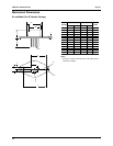
q
J-A
= 41.6°C/W, K (TO-66) pkg.
V
IN
= 40V
V
OUT
= 30V
I
Q
= 1 mA + 75 mA/V
OUT
x 30V
= 3.25 mA*
Solve for I
O
,
= 60 mA – 13 mA ~ 47 mA
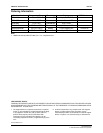
If this supply current does not provide at least a 10% margin
under worst case load conditions, heatsinking should be
employed. If reliability is of prime importance, the multiple
regulator approach should be considered.
In Equation 1, q
J-A
can be broken into the following compo-
nents:
q
J-A
= q
J-C
+ q
C-S
+ q
S-A
where
q
J-C
= junction-to-case thermal resistance
q
C-S
= case-to-heatsink thermal resistance
q
S-A
= heatsink-to-ambient thermal resistance
q
JA–
T
J
T
A
–
P
D
------------------=
P
D
T
J
T
A
–
q
JA–
------------------=
V
IN
V
OUT
–()I
O
V
IN
I
Q
´+´=
I
O
T
J
T
A
–
q
JA–
V
IN
V
OUT
–()
-------------------------------------------------
V
IN
I
Q
´
V
IN
V
OUT
–()
-----------------------------------–=
I
O
150°C 125°C–
41.6°C/W 10V´
-----------------------------------------
40 3.25´ 10
3–
´
10
----------------------------------------–=
———————————————
*The current drain will increase by 50mA/V
OUT
on positive side and 100mA/V
OUT
on negative side