RC4194 PRODUCT SPECIFICATION
13
Mechanical Dimensions (continued)
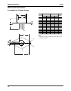
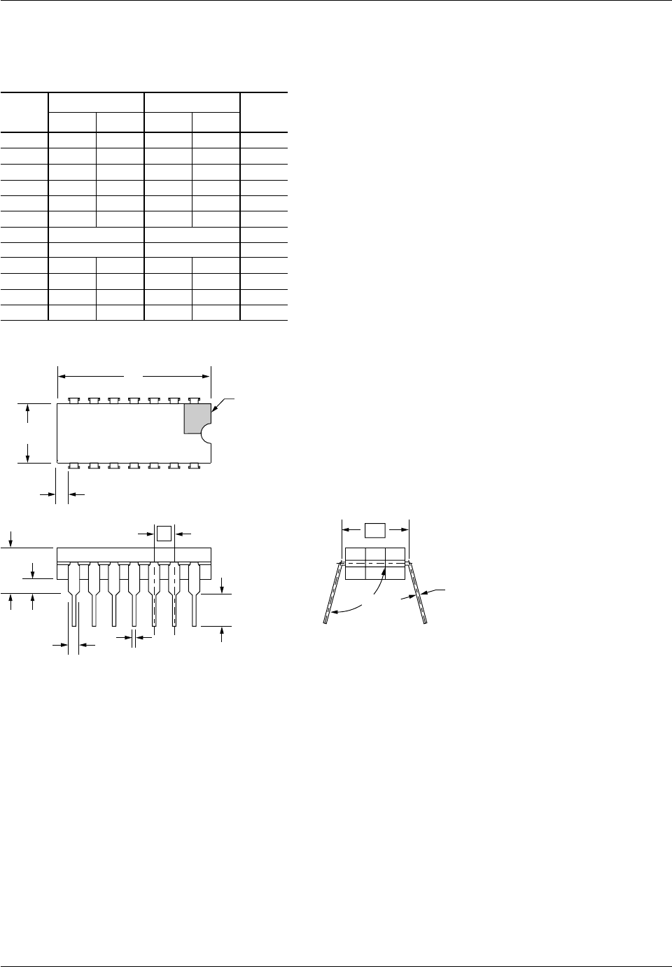
14-Lead Ceramic DIP Package
A — .200 — 5.08
Symbol
Inches
Min. Max. Min. Max.
Millimeters
Notes
b1 .014 .023 .36 .58
.065 1.65
b2 .045 1.14
c1 .008 .015 .20 .38
E .220 .310 5.59 7.87
e
.100 BSC 2.54 BSC
L .125 .200 3.18 5.08
.015 .060 .38 1.52
.005 — .13 —
3
6
8
4
8
2
4
5, 9
eA
.300 BSC 7.62 BSC
7
Q
s1
90¡ 105¡ 90¡ 105¡
a
D — .785 — 19.94
Notes:
1.
2.
3.
4.
5.
6.
7.
8.
9.
Index area: a notch or a pin one identification mark shall be located
adjacent to pin one. The manufacturer's identification shall not be
used as pin one identification mark.
The minimum limit for dimension "b2" may be .023 (.58mm) for leads
number 1, 7, 8 and 14 only.
Dimension "Q" shall be measured from the seating plane to the base
plane.
This dimension allows for off-center lid, meniscus and glass overrun.
The basic pin spacing is .100 (2.54mm) between centerlines. Each
pin centerline shall be located within ±.010 (.25mm) of its exact
longitudinal position relative to pins 1 and 14.
Applies to all four corners (leads number 1, 7, 8, and 14).
"eA" shall be measured at the center of the lead bends or at the
centerline of the leads when "a" is 90¡.
All leads – Increase maximum limit by .003 (.08mm) measured at the
center of the flat, when lead finish applied.
Twelve spaces.
NOTE 1
D
E
s1
8
14
7
1
b2
Q
A
e
b1
L
eA
c1
a


