


ENGLISH
HOW TO ASSEMBLE
CAUTION: Assemble the cleaner completely before using.
CAUTION: Moving parts,make sure the on/off switch is in
the off position and stay clear of the brushroll
when plugging in.
Note: Features may vary by model yet all parts assemble the
same.
Remove all components from the carton and check that all of the
parts are available from the parts list on page 8 (or see the quick
start guide).
Have a Phillips screwdriver available (one is NOT provided in the
package)
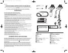
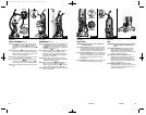
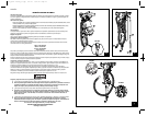
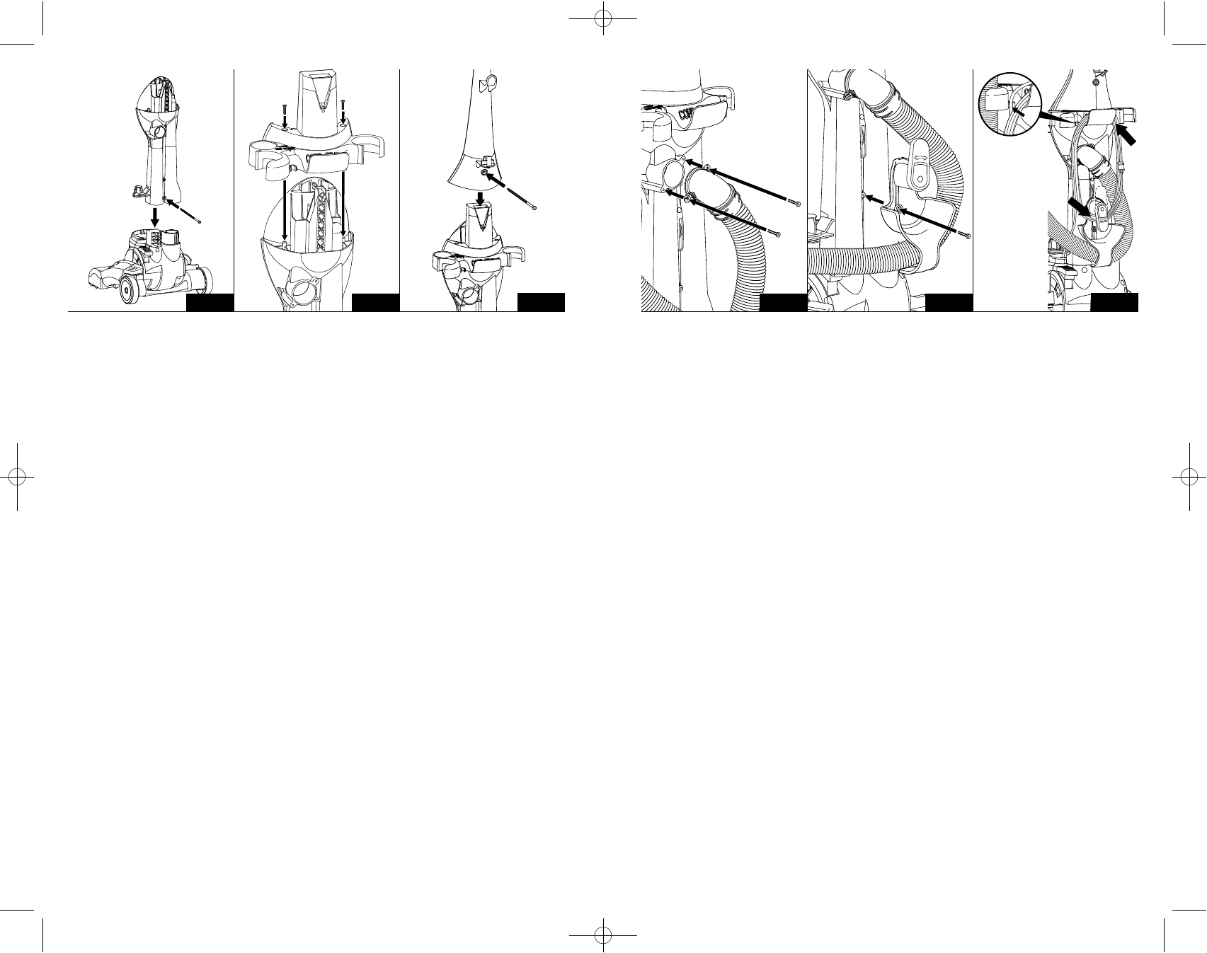
Step 1: Assemble the rear housing
●
I
to the base
●
E
by sliding it
on top of the base and attaching to the base using a long
screw provided
●
●
K2
(FIG. 1).
Step 2: Attach the tool caddy
●
H
to the top of the rear housing
●
I
by sliding it onto the housing, and then attach using
the 2 short screws
●
K1
provided (FIG. 2).
Step 3: Attach the handle
●
G
to top of tool caddy
●
H
by sliding it
downward and then securing with a long screw
●
●
K2
(FIG. 3).
ESPAÑOL
ENSAMBLAJE
PRECAUCIÓN: Ensamble completamente la aspiradora antes de
usarla.
PRECAUCIÓN: Piezas en movimiento.Asegúrese de que el
interruptor de encendido/apagado esté en la
posición apagada y permanezca alejado del
cepillo giratorio cuando enchufe la aspiradora.
Nota: Las características varían según el modelo. Sin embargo,
todas las piezas de ensamblaje son las mismas.
Retire todas las piezas de la caja de cartón y verifique que todas
las piezas de la lista en la página 8 estén disponibles (o vea la guía
de inicio rápido)
Tenga disponible un destornillador Philips (NO se proporciona
uno en el empaque)
Paso 1: Instale el alojamiento trasero
●
I
en la base
●
E
deslizándolo
sobre la misma y fijándola usando el tornillo largo
●
●
K2
proporcionado (FIG.1).
Paso 2: Instale el portaaccesorios
●
H
en la parte superior del
alojamiento trasero
●
I
deslizándolo sobre el mismo.
Alinee los agujeros de los tornillos y fije las piezas
usando los 2 tornillos cortos
●
K1
proporcionados (FIG.2).
Paso 3: Instale la manija
●
G
en la parte superior del
portaaccesorios
●
H
deslizándola hacia abajo y luego
fíjela usando un tornillo largo
●
●
K2
(FIG. 3).
6 7
(CONTINUÉ)(CONTINUED)
FIG. 1 FIG. 2
FIG. 3
●
I
●
K2
●
K2
●
G
●
H
●
K1
●
K1
●
H
●
I
●
E
ENGLISH
HOW TO ASSEMBLE
(continued)
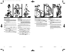
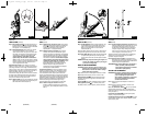
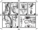
Step 4: Secure the hose assembly to the hose connection on the
rear housing
●
I
with 2 short screws
●
K1
(FIG. 4).
Step 5: Thread the hose inside the lower hose retainer
●
J
and
then attach the lower hose retainer to the rear housing
with a short screw
●
K1
(FIG. 5).
Step 6: Pull the electrical cord up to the cord retainer and firmly
push into the retainer (FIG.6a)
.
This will keep the cord out
of the way for next use.Wrap the cord around the carrying
handle on the tool caddy and then wrap around the cord
release hook.Secure the plug to the power cord with the
notch in the plug to prevent unwinding (FIG. 6).
ESPAÑOL
ENSAMBLAJE
(continué)
Paso 4: Fije el conjunto de la manguera a la conexión de la
manguera en el alojamiento trasero
●
I
usando 2 tornillos
cortos
●
K1
(FIG. 4).
Paso 5: Pase la manguera dentro del conjunto inferior del soporte
de la manguera
●
J
y luego fije el conjunto inferior del
soporte al alojamiento trasero usando un tornillo corto
●
K1
(FIG. 5).
Paso 6: Tire del cordón eléctrico hasta el retenedor del cordón y
oprima firmemente hacia adentro del retenedor (FIG. 6a).
Esto mantendrá el cordón fuera del paso para el próximo
uso. Enrolle el cordón alrededor de la manija de
transporte en el portaaccesorios y luego enróllelo
alrededor del gancho de liberación. Fije el enchufe al
cordón usando la muesca del enchufe para evitar que se
desenrolle (FIG. 6).
FIG. 4 FIG. 5
FIG. 6
(CONTINUED) (CONTINUÉ)
FIG. 6a
●
K1
●
K1
●
J
●
K1
●
I
77418_Rev2 4700OG_r1.qxp 8/1/08 1:04 PM Page 6