


035-18496-000-C-1102
Unitary Products Group 9
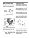
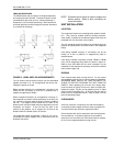
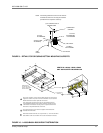
LB600 MOTOR ARRANGEMENTS
The LB600 unit is shipped with the motor mount in the stan-
dard location as shown in 2.
If this is the desired position, the motor mounting assembly is
already in the correct position and the motor and drive pack-
age can be installed without modifications.
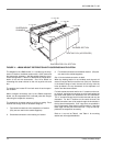
RE-LOCATING THE LB600 MOTOR MOUNTING PLATE
The motor mounting plate can be re-located in three alternate
positions:
ALTERNATE POSITION ONE
For locating motor mounting plate in alternate position one,
see 3 and re-locate as follows:
1. Remove pivot bolts from the mounting plate.
2. Remove the mounting plate from the adjustment screws.
3. Rotate mounting plate 180.
4. With pivot bolts removed in Step 1 fasten the mounting
plate to alternate position No. one.
5. Fasten mounting plate to the adjustment screws.
ALTERNATE POSITION TWO
The motor mounting plate, the pivot bolts and the adjustment
screws can be moved into a position similar to the one shown
as standard in 3 but under the other blower scroll. The frame-
work under each blower scroll has the same bolthole
arrangement.
ALTERNATE POSITION THREE
The motor mounting plate, the pivot bolts and the adjustment
screws can be moved into a position similar to the one
detailed in alternate position one but behind the other blower
scroll. The framework behind each blower scroll has the
same bolthole arrangement.
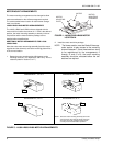
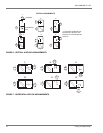
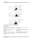
AIR DISCHARGE CONVERSION
LA360/LB360/LB480 AIR DISCHARGE
The LA300 LB360 and LB480 units are shipped for upflow
operation, but may be converted for any of the illustrated air
discharge patterns shown in 7 and 8. Convert as follows:
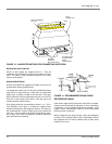
1. Remove the panels from the blower section.
2. Remove the Phillips machine screws located inside cas-
ing corner angles that hold the coil and blower sections
together.
3. Rotate the blower section for the desired air discharge
pattern.
NOTE: Before proceeding to step 4, see the section
on the blower motor mounting locations and
mount the blower motor in the desired position.
4. If accessory heating coils are used, mount heating coil
between cooling coil and blower sections. Screw fasten-
ing locations are the same for all sections and heating
accessories. If heating coils are not used, fasten coil
section to blower section with machine screws removed
in step 2.
5. Before replacing panels, see duct connections and drain
connections.
6. Replace panels.