


035-18496-000-C-1102
14 UnitaryProductsGroup
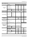
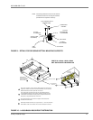
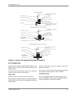
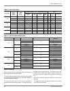
The weights for the LB600 shown in 11 include only the evap-
orator coil section, the blower section with a 10HP motor and
the suspension accessory. Add the weights listed for a hori-
zontal arrangement in Table 4 to determine the weight distri-
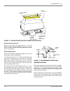
bution of the unit with accessories. See 12 for details on
connecting the center channel to the unit at points one and
two.
The weights are located 5" from both ends of each suspen-
sion channel.
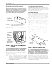
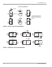
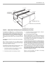
When arranged horizontally (see 8) the LB600 evaporator
blower can be suspended from overhead joists with hanger
rods using the suspension accessory.
The suspension channels require no drilling or cutting. Each
channel has enough holes in its bottom flange for:
1. Four bolted connections to the evaporator coil section.
(Only two are used on the outside supports)
2. One bolted connection to the heating coil section.
3. Four bolted connections to the blower section. (Only two
are used on the outside supports)
See 12 for the bolted connection in detail.
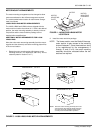
When the heating section is not included, each channel will
extend 3" beyond the front and the rear of the unit. Boltholes
inthebottomflangeofeachchannelwillstillalignwiththe
holes provided in the top framework of the evaporator coil
section and the blower section.
For both outside channels and for the 1" locations on the cen-
ter channel, the bolted connections are to be made where the
top sheet metal panels are attached to the unit framework.
The ¼" screws and cage nuts must be removed and may be
discarded. For the 2" locations on the center channel, the
bolted connections are to be made through the knockouts in
the top sheet metal panels. 5/16" cage nuts are provided in
the unit framework under these knockout locations. Note that
these cage nuts are part of the basic unit. They are not sup-
plied with the suspension accessory.
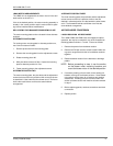
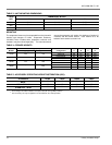
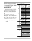
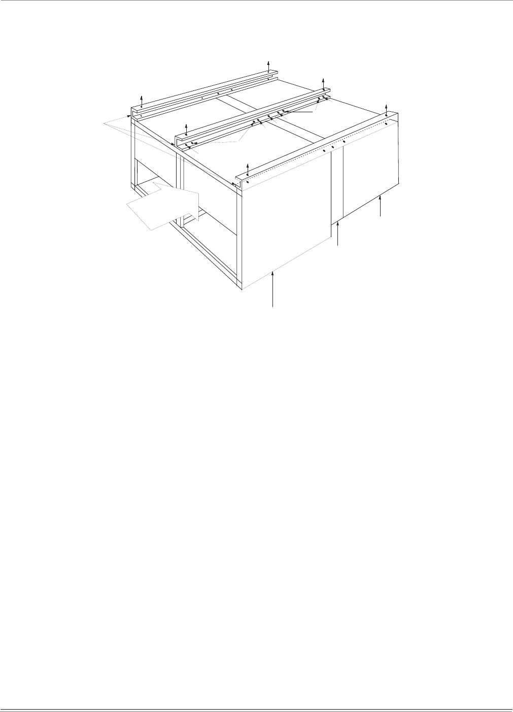
Refer to 11 as well as Table 3 and Table 4 for mounting
details and unit weight distribution.
FIGURE 11 - LB600 WEIGHT DISTRIBUTION WITH SUSPENSION APPLICATION
2
1
2
2
2
1
1
A = 275 LBS.
D = 295 LBS.
E = 300 LBS.
F=310 LBS.
C=285 LBS.
SUSPENSION
CHANNELS
EVAPORATOR COIL SECTION
HEATING COIL (ACCESSORY)
BLOW ER SECTION
B=280 LBS.
AIR
IN