


24632-0-0508 Page 13
WARNING: The nearest point of the vent cap should be a
minimum horizontal distance of six (6) (1.83m) feet from
any pressure regulator. In case of regulator malfunction, the
six (6) foot (1.83m) distance will reduce the chance of gas
entering the vent cap.
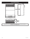
CLEARANCES
GAS SUPPLY (continued)
Pressure Testing of the Gas Supply System
1. To check the inlet pressure to the gas valve, a 1/8" (3 mm) N.P.T.
plugged tapping, accessible for test gauge connection, must be
placed immediately upstream of the gas supply connection to
the appliance.
2. The appliance and its individual shutoff valve must be
disconnected from the gas supply piping system during any
pressure testing of that system at test pressures in excess of
1/2 psig (3.5 kPa).
3. The appliance must be isolated from the gas supply piping
system by closing its individual manual shutoff valve during
any pressure testing of the gas supply piping system at test
pressures equal to or less than 1/2 psig (3.5 kPa).
Attention! If one of the above procedures results in pressures in
excess of 1/2 psig (14" w.c.) (3.5 kPa) on the appliance gas valve,
it will result in a hazardous condition.
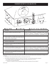
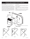
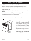
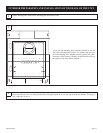
1. In selecting a location for installation, it is necessary to provide
adequate accessibility clearances for servicing and proper
installation.
2. Unit is supported by a wall bracket secured to the wall.
3. The minimum clearances from casing to combustible construction
is 36" (914.4 mm) on top, 6" (152 mm) on each side and
4" (102 mm) from the floor or from the top surface of carpeting,
tile or other floor covering and 0" (0 mm) to rear wall.
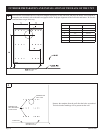
4. The minimum distance from the center of the vent cap to the
nearest outside corner or obstruction is 24" (610 mm).
5. The minimum wall depth is 4 1/2" (114.3 mm) and the
maximum is 12" (304.8 mm). The use of tubes not supplied
by the manufacturer results in unsatisfactory performance.
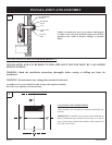
The vent terminal of a direct vent appliance, with an input of
50,000 (14.6 KW) BTU per hour or less shall be located at least 9"
(229 mm) from any opening through which flue gases could enter
a building. The bottom of the vent terminal and the air intake shall
be located at least 12" (305 mm) above grade.
The vent terminal of a direct vent appliance, with an input of
10,000 Btu per hour (3 kW) or less shall be located at least 6"
(150 mm) from any air opening into a building, and such an ap-
pliance with an input over 10,000 Btu per hour (3 kW) but not
over 50,000 Btu per hour (14.7 kW) shall be installed with a 9"
(229 mm) vent terminal clearance and the bottom of the vent ter-
minal and the air intake shall be located at least 12" (305 mm)
above grade.
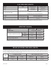
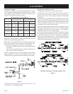
Checking Manifold Pressure
Both Propane and Natural have a pressure regulator attached to
the gas valve. Natural gas models will have a manifold pressure
of approximately 4.0" w.c. (.996 kPa) at the valve outlet with
the inlet pressure to the valve from a minimum of 5.0" w.c.
(1.245 kPa) for the purpose of input adjustment to a maximum of
10.5" w.c. (2.61 kPa). Propane gas models will have a manifold
pressure approximately 10.0" w.c. (2.49 kPa) at the valve
outlet with the inlet pressure to the valve from a minimum of
11.0" w.c. (2.739 kPa) for the purpose of input adjustment to a
maximum of 13.0" w.c. (3.237 kPa).
A 1/8" (3 mm) N.P.T. plugged tapping, accessible for test gauge
connection, is located on the side of the gas pressure regulator.