


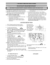


5. VENTING
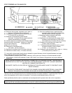
WARNING; THIS APPLIANCE HAS BEEN DESIGNED TO OPERATE BY DRAWING COMBUSTION AIR
AND DILUTION AIR FROM THE ROOM. IT IS ALSO DESIGNED TO DRAW ROOM AIR FOR PROPER HEAT
CIRCULATION FROM THE SIDES OF THE UNIT. BLOCKING OR MODIFYING THE LOUVERS IN ANY WAY
CAN CREATE HAZARDOUS SITUATIONS, EITHER THROUGH POOR VENTING OR BY OVERHEATING. IT
IS IMPORTANT THAT THIS UNIT HAS SUFFICIENT AIR CIRCULATION FOR PROPER VENTING AND
COMBUSTION. PROVISIONS MUST BE MADE FOR THE SUPPLY OF ADEQUATE COMBUSTION AND
VENTILATION AIR. THESE OPENINGS MUST NOT BE BLOCKED.
THE APPLIANCE MUST NOT BE CONNECTED TO A
CHIMNEY FLUE SERVICING A SEPARATE SOLID FUEL
BURNING APPLIANCE.
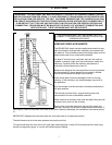
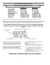
VENTING FIREPLACE INSERTS
The ENVIROGAS insert may be installed and vented into any
solid fuel fireplace that has been installed in accordance with
the National, Provincial/State and local building codes and has
been constructed of non-combustible materials.
An listed 4" chimney liner, seal plate, and rain cap must be
installed, to ensure a tight seal, top performance, safety and
efficiency. Carefully follow the chimney manufacturer’s
instructions that accompany the liner kit.
Measure the height of the chimney before hand and purchase
the appropriate kit. Never attempt to over stretch a flexible
liner to accommodate the height of the chimney.
Install a seal plate to prevent leakage of room air through
chimney. If the chimney is not sealed damage may occur to
the appliance.
Any flue damper must be removed or blocked permanently in
the open position.
The chimney must be clean, in good working order and
constructed out of non-combustible materials.
Make sure that all chimney clean outs are tightly fitting and will
not permit air to leak into the chimney.
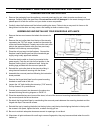
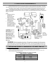
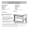
Remove the vent collar plate from the top of the insert and
connect it securely with at least 3 sheet metal screws and a 4"
hose clamp. Check for any tears in the liner at this point. (See also Assembly and Installation Instructions section
3.)
Figure 7
IMPORTANT: Replace the screw that holds the vent collar plate in it's approved position.
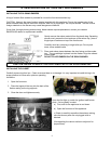
The draft hood must be in the same pressure zone as the air inlet.
To inspect draft from the front of the unit, open right side hinged flap. Locate 3/8” tube and check for draft using
smoke or magnehelic gauge. A vacuum will indicate proper drafting.
7