


10. GAS LINE CONNECTION
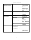
ORIFICE SIZES, PRESSURE AND BTU’S
NATURAL GAS
PROPANE GAS
FRONT BURNER #48 (1.93 mm) #55 (1.32 mm)
REAR BURNER #41 (2.49 mm) #54 (1.40 mm)
Manifold pressure. 3.8” wc (.95 kpa) 11” wc(2.74 kpa)
Min. Manifold pressures. 1.1” wc (.27 kpa) 2.7” wc(.67 kpa)
Supply Pressure. 7.0” wc (1.74 kpa) 12” wc (2.98 kpa)
Min. Supply pressures. 5” WC (1.25 kpa) 11.5” WC (2.86 kpa)
Max. BTU/H Input. 38,000 Btu/h (11.1 kW) 38,000 Btu/h (11.1 kW)
Min. BTU/H Input. 20,000 Btu/h (5.9 kW) 20,000 Btu/h (5.9 kW)
Output fan off 27,800 Btu/h (8.14 kW) 28,900 Btu/h (8.46 kW)
Output fan on 29,400 Btu/h (8.6 kW) 30,300 Btu/h (8.86 kW)
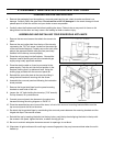
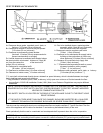
WARNING; Only persons licensed to work with gas piping may make the necessary gas connections to this appliance.
NOTE: The gas line connection may be made using 3/8" rigid tubing or an approved flex connector. Since some municipalities
have additional local codes it is always best to consult your local authorities and the CAN/CGA-B149 (1 or 2) Installation Code.
For USA gas installations follow either local codes or the current edition of the National Fuel Gas Code ANSI.Z223.1.
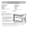
UPON CONNECTION MARK APPROPRIATE FUEL TYPE ON CANADIAN STANDARDS
ASSOCIATION RATING LABEL LOCATED ON THE INSIDE OF THE RIGHT HAND SIDE
PANEL.
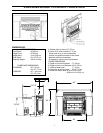
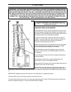
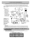
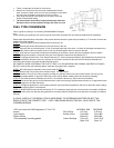
Manifold Pressure Tap. Inlet Pressure Tap.
Millivolt Terminals
Pilot Adjustment screw. "HI-LOW" Burner Gas Knob. Pilot "ON-OFF" Gas Knob.
The appliance and its individual manual shutoff valves
must be disconnected from the gas supply piping system
during any pressure testing where the pressure exceeds
1/2 PSIG (3.45 kpa) or damage will occur to the valve.
The appliance must be isolated from the gas supply piping
system by closing its individual manual shutoff valve
during any pressure testing of the gas supply piping
system at test pressures equal to or less than 1/2 psig (3.5
kpa).
When using copper or flex connectors use only fittings
approved for gas connections.
TO TEST
The pressure taps are located in the top right corner on
the valve face (right - inlet, left - manifold pressure).
• Turn set-screw counter clockwise to loosen, 2 turns.
• Place 5/16" hose over pressure tap system.
• When finished, releases pressure, remove hose &
tighten set-screw.
Always check for gas leaks with a soap and water solution
after completing the required pressure test.
NEVER USE AN OPEN FLAME FOR LEAK TESTING
12