


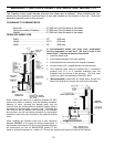

ELECTRICAL COMPONENT FUNCTIONS
The following is a list of electrical components and their functions on the ENVIROFIRE EF-IIIi Bay pellet stove.
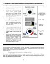
1. CONVECTION FAN CONTROLLER
This controller is responsible for varying the speed of the convection blower. The stove does have a fan control
over-ride. Should the convection blower be set on low and dial-a-fire set on high, the convection blower will by-
pass the fan controller and go to high. This will cool the stove until control is given back to the fan controller. To
eliminate possible cycling of the convection blower turn up the fan speed proportionately to the dial-a-fire.
2. AUGER PULSE LIGHT
This light will flash in conjunction with the pulses to the auger.
3. START-UP SWITCH
When this momentary contact switch is pressed it will initiate a 15 minute start-up cycle including the ignitor.
4. DIAL-A-FIRE (HEAT OUTPUT CONTROL)
This unit is responsible for controlling the timing of the auger motor. When turned clockwise it will cause the OFF
time between auger pulses to shorten, resulting in more heat output and pellet consumption. Turn the knob
counter-clockwise and the reverse will happen. When it is turned fully counter-clockwise past the click, the auger
motor will be off.
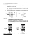
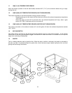
5. CONVECTION BLOWER
This blower fan (mounted on the right side of the stove) draws room airs from the back of the stove and passes
the air through the heat exchanger tubes and back into the room. The units sealed system keeps the room air
separate from the combustion air. The convection fan controller controls this fan’s speed.
6. EXHAUST/COMBUSTION BLOWER
This constant speed fan (mounted on the left side of the stove) is responsible for drawing the outside fresh air into
the combustion chamber for burning. The hot air then continues to be drawn over the heat exchanger tubes and
into the exhaust channel. It is then pushed out through the exhaust system.
7. AUGER MOTOR AND AUGER
The 1 rpm auger motor is responsible for turning the auger, which in turn transports pellets to be dropped into the
burn pot. The auger motor’s control is handled by the timing control module and Dial-A-Fire.
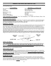
8. TIMING CONTROL MODULE
The timing control module is mounted uppermost, on the right rear pillar of the stove. The module controls the
switching of power to the auger. The module’s switching duty cycle is controlled by the dial-a-fire.
9. START-UP TIMER
This 15 minute one-shot timer bypasses the 140°F (60°C) temperature sensor allowing the stove to operate when
cold. The timing cycle is initiated by pressing the start-up switch. The 15 minute timer is
located right under the
timing control module on the right side pillar. This unit is also responsible for initiating the ignition cycle.
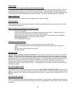
10. 200°F (93°C) MANUAL RESET TEMPERATURE SENSOR
This sensor (located on the right side firewall) has a red push button located in its center. This is a safety device.
In the event that the convection blower fails, this sensor will overheat and shut off power to the auger motor.
10