


MAINTENANCE
CAUTION: UNPLUG THE UNIT PRIOR TO ANY SERVICE WORK!
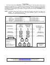
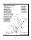
SEE EXPLODED DIAGRAM (ILLUSTRATION 6) FOR PARTS REFERENCE
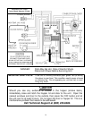
Parts Orders: (800) 516-3636 www.englanderstoves.com Questions: (800) 245-6489
NOTE: Visit our web site for downloadable maintenance sheets and/or a service video that details
and illustrates the following maintenance tasks.
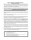
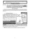
Rear Panel Removal
WARNING: To perform any maintenance inside the rear of the unit, the stove must be out
(no fire), cooled down and unplugged. Electrical shock can occur if the unit is
not unplugged from power.
To remove the rear panel, simply loosen the eight (8) screws (size 5/16”) and flex the panel. The
panel should come off without fully removing the screws.
Instructions for maintenance and part replacement procedures can be found on:
www.englanderstoves.com
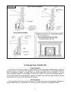
Auger Motors
The Auger Motor and gearbox are one complete assembly (Part # PU-047040), and can be
removed by disconnecting the power leads and loosening the (
5
/
16
” head) set bolt in front of the
assembly. This bolt tightens down on the flat side of the gear shaft and locks the gear shaft and
auger shaft together – once the bolt is loosened, the entire assembly will slide from the locking collar.
There are two motor assemblies on the unit, and both rest on a shelf when not in operation. When
replacing a motor, the assembly should always be placed to rest on this shelf prior to starting the
unit.
Auger Bearings and Auger Shafts
The auger bearings (Part # PU-UCF204-12) are a sealed unit and do not require lubrication. To
replace the Top Auger, all the fuel must be removed from the hopper as well as from the Top Auger
assembly. Once this is done, the four bolts that hold in the bearing can be removed, followed by the
complete auger assembly. Loosen the two (2) set screws with a 1/8” allen wrench, which will
disconnect the bearing from the shaft (the bearing assembly and auger assembly can be replaced by
reversing this procedure). When placing the auger assemblies in the unit, always tighten the four
bolts in a diagonal pattern to ensure the bearings and shafts are aligned properly.
NOTE: Follow the same procedure to work on the bottom auger, with the exception that the pellets
do not have to be removed from the hopper.
Convection Blower
The Convection (room air) Blower (Part # PU-4C447) is located on the left side of the unit and
can be removed by disconnecting the power leads and removing the four mounting screws. Once
this is done, the blower will slide out of the stove. This procedure can be reversed to install a new
blower.
15